

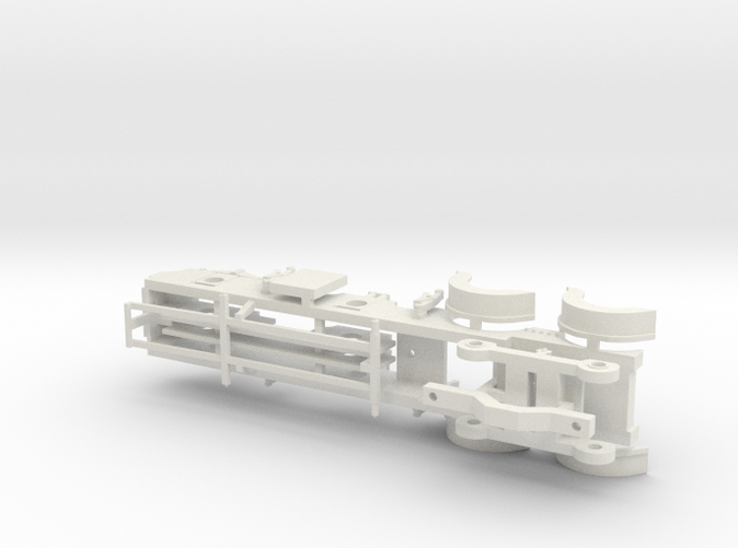
Cambrian Class 61 - P4 CHASSIS
Made by
Have a question about this product?
contact the designerProduct Description
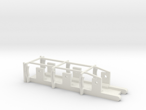
P4 chassis for the Cambrian Class 61 Locomotive.
Frame width 16mm's, worked out using 17.75mm Back to Back settings for brake pads etc.
IMPORTANT NOTE: Both textual and scale drawings don't always seem to agree on what
wheelbase and diameter bogie wheels the Furness Railway K2 (21 Class) and the Cambrian
Railways Class 61's ran with. For the Bogie wheel diameter many sources say 3' 6" but other
sources say 3' 0", similarly the
wheelbase is disputed between
5’ 6” + 6’ 6½” + 8’ 3”
5' 9" + 6'6" + 8'6"
&
5’ 9” + 6’ 8” + 8’ 6”
The Cambrian Class 61 available from SCC have been built and designed
with the top wheelbase and is designed to take 3' 6" Bogies.
As all the Class 61 chassis and bodies are common to each other, any will fit in combination as they
are interchangable.
For more information on the discrepancies and to help you decide, you may look here for
more information...
http://www.rmweb.co.uk/community/index.php?/topic/106162-scc-sparkshot-custom-
creations/page-2#entry2146281
or here...
http://www.scalefour.org/forum/viewtopic.php?f=30&t=4577&start=25
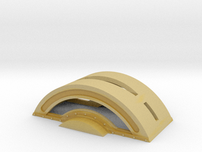
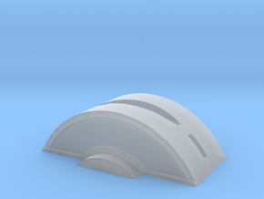
As the frame is designed to take 3' 6" bogie wheels the top of the frames will be very thin and weak. Neatly
cutting the frame here and glueing the front section that goes above the front bogie wheel
to the loco body may be a consideration and you may need to file a little extra clearence for the wheels, same for the optional bogie splashers. The real thing was a tight fit too.
Also prototype photo's sometimes showed the
optional bogie splashers removed (on the K2 at least), unless you have generous curve radii
these will likely have to be ommitted.
On the EM and P4 versions these have been pulled
inwards by 0.7mm's. As neither are to perfect width due to thickness and bogie movement, If you would like Optional Bogie Splashers pulled in or out to a
different degree please contact me and It'll be arranged. The 00 ones are 5.7mm's width.
Finally a more solid answer to the wheelbase issue between the Furness K2's and Cambrian Class 61's has been found with much thanks and credit to Mike Peascod of the Cumbrian Railways Association. Here is His PDF he kindly compiled from a few sources to show the different wheelbases that existed as genuine variation...
http://www.scalefour.org/forum/download/file.php?id=10574
As a reminder, the Cambrian Class 61 bodies and the chassis are designed to fit the
5’ 6” + 6’ 6½” + 8’ 3”
wheelbase and will not fit the K2 chassis that has a wheelbase of 5’ 9” + 6’ 8” + 8’ 6”.
If you would like a Cambrian Class 61 with the same wheelbase as the K2 then please get in touch and will upload one as it is ready just in case.
-
Note: This is a fixed chassis so reaming
out the axle holes downwards and
allowing the bushes to move freely may
help things. The dummy hornblocks
have 'etched' lines cut into them to aid a
saw should you wish to remove these and
add real brass sprung hornblocks in their
place. If using a FUD chassis the chassis
will be weak until the replacement
hornblocks are properly installed.
Chassis more readily set up for springing
are being worked on as a future
development.
The Bogie and Brake Gear is sprue joined
to the top and sides, as are the optional
Splashers (Wheel Arches) for the Bogie
Wheels. Unless you have very generous
radius curves these likely will have to be
omitted from the final build. Some
prototype photographs showed the
locomotive without them though. Cut
these components off and keep them
safe. The chassis is printed square,
however the rear frame spacer is sprued
on the left side for you to add where you
want depending on your gearbox choice.
1/8th / 3mm 'Top Hat' Bearings need to be
glued into the axle holes for the 24mm /
6FT Driving Wheels and for the 3ft 6inch Bogie
Wheels you can fit 2mm 'Straw Hat'
Bearings once the holes have been
reamed out to accomodate them. Test
builds show that, like the tenders it isn't
really needed and they will roll nicely
anyway, but the choice is yours.
The frames have sprued to the insides two
x 1mm thick, thickening lengths that if
fitted will make the frames 1mm's thicker
either side. Your choice of gearbox will
dictate if you use these or how much of
them you use as you can cut them to size
to thicken up most of the frames and
leave a thinner area for a gearbox if
needed.
For the Bogie to work there are two
options:
A) A thin 'cheesehead' bolt with a
approximately a 1.5mm diametre thread
(such as a 10 or 11BA) can pe pushed
through the underside of the Bogey up
into the bottom of the Loco Body under
the smokebox and screwed in, this will
allow the Bogey to turn in its arc and also
provide lateral movement. Adding a weak
spring (like those in sprung coupling
packs) with a thin washer soldered to it
providing a slide helps.
B) Possibly the easier option, screw the
chassis to the body with a 10 or 11BA bolt
using the holes underneath the
Smokebox, then using the optional Pivot
Arm that was also sprue joined to the
Bogie, screw this upwards into the rear
chassis hole located in front of the front
Driving Wheel, then at the other end
screw a bolt downwards into it and
through the Bogie, finally cap it with a
nut and secure with a paint blob. The
clearence between the top of the bolt
head and the bolt head that joines the
chassis to the body is minimal. If it
conflicts a few gentle passes with a fine
file will sort this easily. The Pivot Arm is
printed to the correct orientation so be
sure to fit it the correct way!
The chassis will self tap.
For pick ups, crank pins, motors,
gearboxes etc and the Coupling Rods
(available on this site), the same methods
used for conventional kit building need
to be applied, and there are many options.
For the test builds the 'traditional'
method of PCB strips and 0.45mm brass
wire/rod was used to good effect.
General note: Once the chassis is built and working you may need to file/shave a small amount of material from under loco body for the coupling rods due to the running plate needing to be printed thicker than a scale reality. On some models sometimes the inside edge of the splashers need a small amount shaving away too (moreso in P4). A few passes with a brass brush in a mini drill makes this a 2 second job though.
Initial builds were done with Alan Gibson wheels that have a 14" 'throw' on the crankpins. The Cambrians's had a throw of 12" and so this also explains some of the shaving of material needed if using 14" throw wheels. Alan Gibson do currently do wheels with a throw of 13" so these will work even better needing less shaving.
Alan Gibson code =
4872V, 6' 0" / 24.0mm, 20 spoke, LNER B13, Class Plain, PB, 13" (or the S4 equivalent)
TIP:
To allow your model to be motorised
without having to hack away at the
underside of the firebox or boiler as is
common with many of kits depending
what parts you use, a 'Roadrunner +'
Gearbox from High Level will fit nicely,
using a drive extender may make things
easier too, especially if fitting a fly wheel.
These components were used in the
research and development trial builds.
EDIT: Future builds have shown that a London Road Models GB4 Single stage Motor Mount (Gearbox) fits better, is cheaper and quicker to build. As with all loco kits the choice is entirely yours though.
http://traders.scalefour.org/LondonRoadModels/various/components/
For wheels, axles, crankpins etc
Alan Gibson is a great resource
...as is Markits
http://www.markits.com
For Motors and Gearboxes, High Level are
recommended.
http://highlevelkits.co.uk/
For crank pins, hand rail rod/wire and
pillars, washers, bearings and other small
sundry items Mainly Trains is a good
website to visit.
http://www.mainlytrains.co.uk/acatalog/i
ndex.html
But of course you can use whatever suits
your needs and preference best,
the above has been typed out to hopefully
aid you should you be new to kit building.
The advantage of these 3D printed kits is
90% of the work is done for you, both on
the body and the chassis.
A video series showing how to build SCC locomotive kits can be found here:

Details

