
Tan Fine Detail Plastic


1/144 Scale Boeing 747 Leading Edge Flaps
Made by
Print With Shapeways
 Choose Your Material
 Choose your color and finish
$30.55
Have a question about this product?
contact the designerYou must be logged in and verified to contact the designer.
Product Description
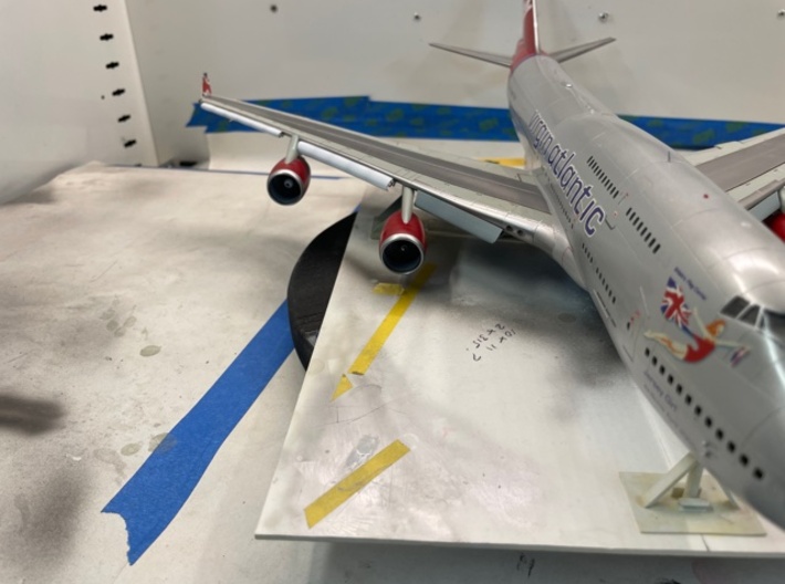
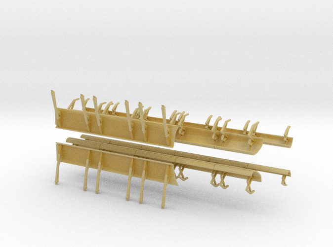
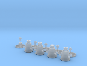
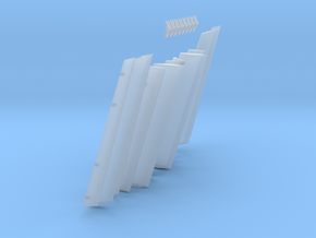
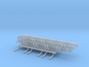
Designed for the Revell 1/144 scale 747-400 series, however these leading edge krueger and variable camber (VC) flaps can be used on any 1/144 scale Boeing 747 series kit (Boeing 747-100, -200, -300, 747SP, -400, -400D and 747-8).
What comes in the kits:
Left Wing Krueger Flaps (section of three flaps)
Left Wing Inboard Variable Camber Flaps (section of five flaps)
Left Wing Outboard Variable Camber Flaps (section of five flaps)
Right Wing Krueger Flaps (section of three flaps)
Right Wing Inboard Variable Camber Flaps (section of five flaps)
Right Wing Outboard Variable Camber Flaps (section of five flaps)
Installation involves cutting the leading edge sections out of the wing. I recommend doing this prior to joining the upper and lower wing parts together so any desired detailing of the visible inner wing area can be done. If the model is a static ground display this can be skipped as the area is not visible.
Paint the leading edge sections and wings prior to assembly. When installing, simply offer up the parts to the correct section of the wing and glue the retraction fittings in position using fine super glue. Use reference photos to obtain the correct angles.
This kitset is recommended to be used with kit set '1/144 Scale Boeing 747 Trailing Edge Flaps' also available on Shapeways.
Modlling tip - if you are displaying a B747 shortly after touch-down/on roll-out the outboard VC flap sections should be OPEN only. The inboard Krueger flaps and inboard VC flaps should be closed or closing. This is a feature of the B747 to prevent damage occuring the the Krueger flaps and inboard VC flaps during reverse thrust deployment.
Bruce Goorney 1:12 PM (17 minutes ago) to Andrew Andrew, It appears the installation instructions that I painstakingly put on the website have disappeared at some point when they have done a software update! [u]Flap Sections and Orientation:[/u]You will have 12 flap sections in total. Take the longer sections and shorter sections lay them out with the thickest section flap in the center of each (see image below as a guide). This is the mid flap.
The three flap parts will slide together to form a single section that is similar to what you should have cut out of the wing. Note - when cutting out the flap sections from the wing, the upper wing surface panel line shows a single flap section and the lower shows two. When trimming out the lower, leave the flap faring in position initially. The shorter flap sections are inboard flaps. Take one of the inboard flaps and orientate against your model wing so the flat side of the flap is lower and the bulged side is upper. This will indicate now if you have the left or right side inboard mid flap. Repeat this process until you have all four mid flaps laid out. Take the thinner flap section that corresponds in length to the mid flap and you will see, like the mide flap, there is also a flat side. Orientate this using the shape of the flap as a guide to work out whether it is the left side or right side. Here is an illustrated guide that will help you:
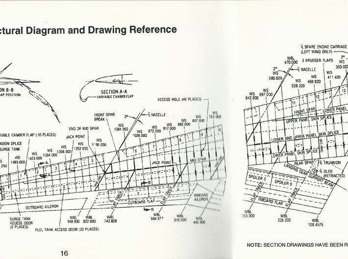
If you are setting up the flaps for a landing configuration, you will insert four rods into the mid flap part. I will cover this shortly. The fore flap is the remaining flap section that is curved aerofoil in shape on both sides. When retracted, this flap is not visible from the upper or lower side of the wing. When fully extended the configuration is as below:
Use the illustration above to calculate your angles. This was from a Boeing 747 document and (speaking as a aero engineer with over a decade on the type) is accurate for your model. [u]Fabrication of the flap tracks:[/u]The tracks are made from "I"section styrophone or brass rods. I used the smallest I Beam that Evergreen make. It should be 1.5 mm. You will see the flap fairings have a recess on the model. use these as a guide for the length and also the point of attachment to the wing. The track end is curved down and should be no longer than where the fairing starts sloping down at the aft end. Use heat to tightly curve the I beam down, and trim off tip using this illustration as a guide: Trim off your flap fairings and glue the tracks in place ENSURING they are angled in the same position at the fairings were, and are flat and parallel to the lower surface of the wing. Re-attach the fairings now at an angle of 35 degrees. You need to do this with the lower wing half flat on your work surface and take the 35 degree angle from the work surface. Fill the gap that the 35 degree angle has formed between the forward and aft or the fairing and sand smooth for paint. [u]Flap Fitting:[/u]The flaps attach to the wing from the main flap by means of flap carriages. The fore flaps fit to the forward section of the carriage and are on guides that recess into the forward section of the main flap. The aft flap for easy of the kit, it attached to the main flap with 4 previously mentioned square section rods. The flaps are fitted to the tracks using the carriage fittings supplied in the kit. There should be 8 carriage fittings. They are installed into the recesses on the lower side of the mid flap and are orientated forward at the corresponding angle of the tracks. You may want to dry fit the carriages on the tracks and then attach the mid flap to them in this position to ensure you have them correctly angled. It is very important the angles correspond or the flaps will not sit correctly. Once the carriages are attached correctly, the aft flap should be fitted. The aft flap has the four trimmed out sections on the leading (forward facing) edge. Turn over a mid flap section and you should see four corresponding .5mm x .5mm square recesses in the aft section of the flap. Insert QTY 4 0.5mm section styrofoam or brass rods into the mid flap recesses and when set, trim the sections to approximately 1.5mm proud of the mid flap. You will need to trim further to get the aft flap in the correct position. The trimmed out sections of the aft flap are attached to these rods leaving a uniform slotted gap between the two flaps of around 0.25mm with an angle between the mid and aft flap of 15 degrees (this is maximum flap deployment per the illustration above with flaps at detent 25). *You may find it helpful to make a jig for this. [u]The leading edge flaps must be cut out now[/u]Trim out the leading edge sections which are clearly scribed on the kit lower wing surface. The inboard krueger flaps are closest to the fuselage and there are three per side.
The variable camber flaps are from the inboard pylon going outboard in two sets of 5.
It is easier to trim out the flap including the small section of leading edge forward of the flaps, then carefully trim this strip off and glue it back on the wing when you put the two halves together. It is important that this piece is retained and re-attached!. Glue the two wing sections together at this point then, once set, dry fit the inboard and outboard flap assemblies and orientate the fore flap into position until you are happy with the open slot widths and angles of all the flaps relative to each other and the wing. Once you have the positions as you need them, use tape to hold the positions and then glue the inboard and outboard flap assemblies and the fore flaps into position. The trailing edge flaps are basically done.
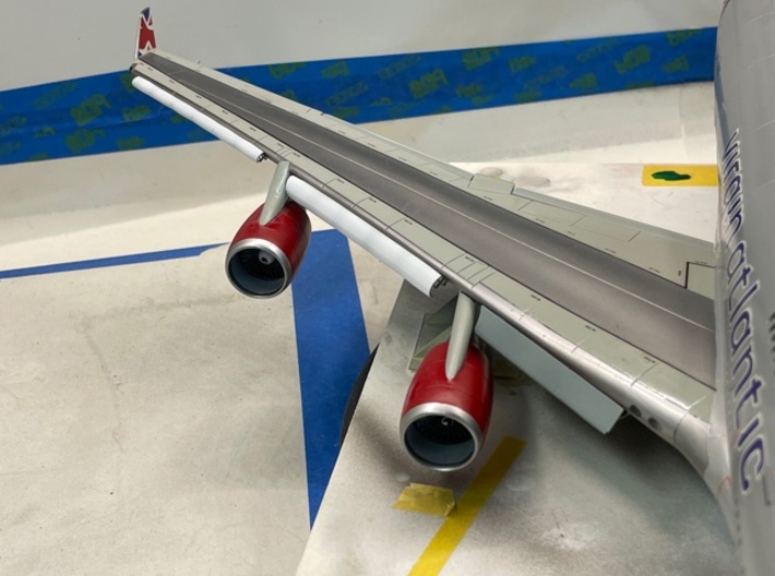
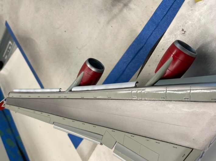
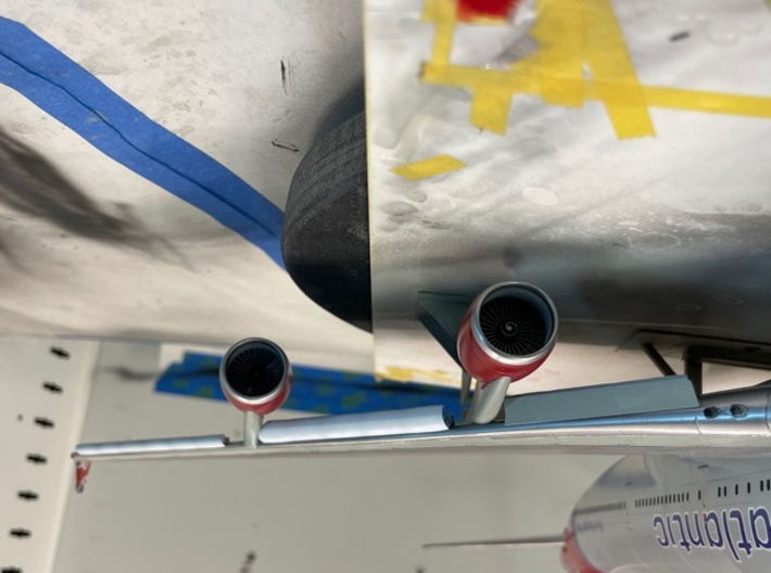
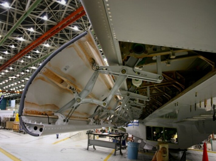
(I added small steel rods to my kit to replicate the ball screws that extend and retract the flaps) [u]Leading Edges:[/u]Do not attempt to install the leading edges until the pylon/engine assemblies are in position and the wings are painted!!! The Leading edges must also be painted prior to fitting as the attachment points are very delicate Install the leading edges to the wings by fitting the leading edge rods to the forward cutout face of the wing. You will have to trim the attachment fittings on the leading edge flaps to fit correctly. Use a thin piece of card between the wing surface and top edge of each flap section to provide the necessary gap. The flaps are angled forwards.
The variable camber flaps are orientated similar to the inboard krueger flaps. The curved end of the flap marries up with the inboard face of the adjacent outer pylon as can be seen on the krueger section above. The very thin set of variable camber flaps have no curved edge and fit to the outer wing section.
What comes in the kits:
Left Wing Krueger Flaps (section of three flaps)
Left Wing Inboard Variable Camber Flaps (section of five flaps)
Left Wing Outboard Variable Camber Flaps (section of five flaps)
Right Wing Krueger Flaps (section of three flaps)
Right Wing Inboard Variable Camber Flaps (section of five flaps)
Right Wing Outboard Variable Camber Flaps (section of five flaps)
Installation involves cutting the leading edge sections out of the wing. I recommend doing this prior to joining the upper and lower wing parts together so any desired detailing of the visible inner wing area can be done. If the model is a static ground display this can be skipped as the area is not visible.
Paint the leading edge sections and wings prior to assembly. When installing, simply offer up the parts to the correct section of the wing and glue the retraction fittings in position using fine super glue. Use reference photos to obtain the correct angles.
This kitset is recommended to be used with kit set '1/144 Scale Boeing 747 Trailing Edge Flaps' also available on Shapeways.
Modlling tip - if you are displaying a B747 shortly after touch-down/on roll-out the outboard VC flap sections should be OPEN only. The inboard Krueger flaps and inboard VC flaps should be closed or closing. This is a feature of the B747 to prevent damage occuring the the Krueger flaps and inboard VC flaps during reverse thrust deployment.
Bruce Goorney 1:12 PM (17 minutes ago) to Andrew Andrew, It appears the installation instructions that I painstakingly put on the website have disappeared at some point when they have done a software update! [u]Flap Sections and Orientation:[/u]You will have 12 flap sections in total. Take the longer sections and shorter sections lay them out with the thickest section flap in the center of each (see image below as a guide). This is the mid flap.
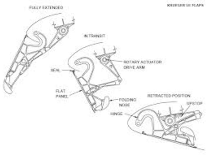
The three flap parts will slide together to form a single section that is similar to what you should have cut out of the wing. Note - when cutting out the flap sections from the wing, the upper wing surface panel line shows a single flap section and the lower shows two. When trimming out the lower, leave the flap faring in position initially. The shorter flap sections are inboard flaps. Take one of the inboard flaps and orientate against your model wing so the flat side of the flap is lower and the bulged side is upper. This will indicate now if you have the left or right side inboard mid flap. Repeat this process until you have all four mid flaps laid out. Take the thinner flap section that corresponds in length to the mid flap and you will see, like the mide flap, there is also a flat side. Orientate this using the shape of the flap as a guide to work out whether it is the left side or right side. Here is an illustrated guide that will help you:
If you are setting up the flaps for a landing configuration, you will insert four rods into the mid flap part. I will cover this shortly. The fore flap is the remaining flap section that is curved aerofoil in shape on both sides. When retracted, this flap is not visible from the upper or lower side of the wing. When fully extended the configuration is as below:
Use the illustration above to calculate your angles. This was from a Boeing 747 document and (speaking as a aero engineer with over a decade on the type) is accurate for your model. [u]Fabrication of the flap tracks:[/u]The tracks are made from "I"section styrophone or brass rods. I used the smallest I Beam that Evergreen make. It should be 1.5 mm. You will see the flap fairings have a recess on the model. use these as a guide for the length and also the point of attachment to the wing. The track end is curved down and should be no longer than where the fairing starts sloping down at the aft end. Use heat to tightly curve the I beam down, and trim off tip using this illustration as a guide: Trim off your flap fairings and glue the tracks in place ENSURING they are angled in the same position at the fairings were, and are flat and parallel to the lower surface of the wing. Re-attach the fairings now at an angle of 35 degrees. You need to do this with the lower wing half flat on your work surface and take the 35 degree angle from the work surface. Fill the gap that the 35 degree angle has formed between the forward and aft or the fairing and sand smooth for paint. [u]Flap Fitting:[/u]The flaps attach to the wing from the main flap by means of flap carriages. The fore flaps fit to the forward section of the carriage and are on guides that recess into the forward section of the main flap. The aft flap for easy of the kit, it attached to the main flap with 4 previously mentioned square section rods. The flaps are fitted to the tracks using the carriage fittings supplied in the kit. There should be 8 carriage fittings. They are installed into the recesses on the lower side of the mid flap and are orientated forward at the corresponding angle of the tracks. You may want to dry fit the carriages on the tracks and then attach the mid flap to them in this position to ensure you have them correctly angled. It is very important the angles correspond or the flaps will not sit correctly. Once the carriages are attached correctly, the aft flap should be fitted. The aft flap has the four trimmed out sections on the leading (forward facing) edge. Turn over a mid flap section and you should see four corresponding .5mm x .5mm square recesses in the aft section of the flap. Insert QTY 4 0.5mm section styrofoam or brass rods into the mid flap recesses and when set, trim the sections to approximately 1.5mm proud of the mid flap. You will need to trim further to get the aft flap in the correct position. The trimmed out sections of the aft flap are attached to these rods leaving a uniform slotted gap between the two flaps of around 0.25mm with an angle between the mid and aft flap of 15 degrees (this is maximum flap deployment per the illustration above with flaps at detent 25). *You may find it helpful to make a jig for this. [u]The leading edge flaps must be cut out now[/u]Trim out the leading edge sections which are clearly scribed on the kit lower wing surface. The inboard krueger flaps are closest to the fuselage and there are three per side.
The variable camber flaps are from the inboard pylon going outboard in two sets of 5.
It is easier to trim out the flap including the small section of leading edge forward of the flaps, then carefully trim this strip off and glue it back on the wing when you put the two halves together. It is important that this piece is retained and re-attached!. Glue the two wing sections together at this point then, once set, dry fit the inboard and outboard flap assemblies and orientate the fore flap into position until you are happy with the open slot widths and angles of all the flaps relative to each other and the wing. Once you have the positions as you need them, use tape to hold the positions and then glue the inboard and outboard flap assemblies and the fore flaps into position. The trailing edge flaps are basically done.
(I added small steel rods to my kit to replicate the ball screws that extend and retract the flaps) [u]Leading Edges:[/u]Do not attempt to install the leading edges until the pylon/engine assemblies are in position and the wings are painted!!! The Leading edges must also be painted prior to fitting as the attachment points are very delicate Install the leading edges to the wings by fitting the leading edge rods to the forward cutout face of the wing. You will have to trim the attachment fittings on the leading edge flaps to fit correctly. Use a thin piece of card between the wing surface and top edge of each flap section to provide the necessary gap. The flaps are angled forwards.
The variable camber flaps are orientated similar to the inboard krueger flaps. The curved end of the flap marries up with the inboard face of the adjacent outer pylon as can be seen on the krueger section above. The very thin set of variable camber flaps have no curved edge and fit to the outer wing section.
Details
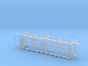
What's in the box:
1/144 747 Leading Edge Flaps
Dimensions:
Success Rate:
First To try.
What's this?
Rating:
Mature audiences only.
