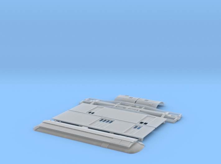
Clear Ultra Fine Detail Plastic


HO Pacific Electric / USMC Portable Substation
Made by
Print With Shapeways
 Choose Your Material
 Choose your color and finish
$117.40
Have a question about this product?
contact the designerYou must be logged in and verified to contact the designer.
Product Description
This is a simple-to-build kit for a Pacific Electric or US Maritime Commission portable substation.
These were placed around the PE system to boost power in places where line voltage was found to be too low. They converted AC "city power" to 600 volts DC, and could be wired together in series to create the 1200 volts needed for the San Bernadino line. They were also used as a stand-in substation when permanent ones were downed for maintenance or repair.
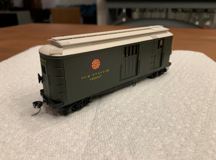
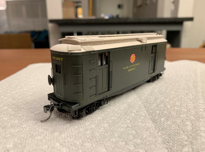
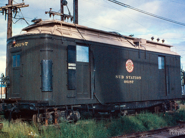
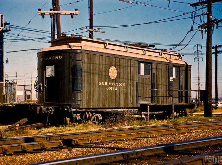
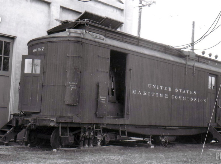
This particular substation model is patterned after the last group of four portables built by the PE for the US Maritime Commission during WW2. They carried numbers 00184 to 00187. Originally they were lettered for the USMC but were later repainted and relettered for the PE, and then MTA. 00186 and 00187 lasted until the end of service in 1961 and could be seen along the Long Beach line, with many photographs taken of them in the area of Dominguez Junction.
Prototype photos shown below are for reference when painting and detailing this model and were scavenged from around the web and I did not keep good notes of from where they came. If they belong to you and you wish to have them credited or removed please reach out.
A shopping list to finish this model:
- .010 phosphor bronze wire for bending into hand-holds - available inexpensively through Tichy Train Group.
- Kadee 561 arch-bar trucks
- Kadee 148 whisker couplers and a scrap of flat plastic to create a lid for the coupler box (short shank may look better) - you can also just use a washer.
- 10 ea 1/4 inch 2-56 screws to attach the body to the floor and hold the couplers.
- Stirrup steps. I use A line stirrups but you can certainly bend your own.
- Two brake wheels - I scrounged my parts box and found a couple atlas RS3 brake wheels, but Kadee 2040 Ajax brake wheels would be appropriate for these.
- Paint - these were probaly box car red when assigned to the USMC, but wore pullman green with a tan roof in PE paint. I used scalecoat2 pullman green for the sides and TruColor flat tan for the roof. The floor and the scuff shields next to the door openings should be black.
- Decals - I used items from two microscale sets to decal the model shown. Set 87-589 has the fast freight shields. Set 87-563 was used for the lettering. I'm resourceful (read as cheap) and used individual yellow letters and numbers from an old almost-used-up 87-563 sheet I had around, but had to make the "B"s from a "P" and half of another letter to make the lower lobe of the B, as no Bs could be found anywhere on that sheet. That microscale sheet also has the Maritime Commision lettering if you choose to make yours a WW2 era model.
Assembly instructions:
1. Scrub all parts with un-diluted simple green and a tooth brush. I use a sonicare electric toothbrush. Rinse while scrubbing with the hottest water you can keep your hands in without getting scalded. Repeat for as long as you feel any waxy coating on the parts. This is critical for paint adhesion.
2. Tap the 8 holes in the mounting pads found on the back sides of the side walls with a 2-56 tap. Also tap the coupler pocket holes and the truck mounting holes with the 2-56 tap. Go easy and don't force it or you'll crack the model.
3. The hand holds and roof grabs have thier holes "pre-drilled" in the model to accept .010 wire. I use a Micro Mark handhold bending tool to bend my grabs in exact lengths so they look uniform. Make the legs a bit long to protrude into the carbody for easy and invisible gluing. I use CA (super glue) from the inside of the model to hold the grabs in place. If you want to buy one of these bending tools, there is a 10% discount available if you use the discount code "boulder" (works as of 10/1/20).
4. I paint the model in parts so the only masking required is to get the black on the scuff plates next to the doorways. You can paint it whole if that's your perogative, but I prefer the easy way.
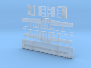
5. Assemble the model. I glued the ends to the roof first. There are locator pegs to aid in alignment. I glued the pegs and the seam between them first, so that the outer corners of the ends could still be manipulated a bit to get the sides in good alignment. To get a sufficient amount of glue without going overboard, I put some CA in an old plastic water bottle cap, then use a toothpick to dab the glue onto the seams of the carbody from the inside. The green label Zap is my favorite for this. The red lable is a bit runny and tends to glue my fingers to the model.
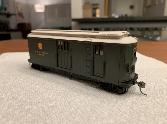
Once the ends are in, the sides can be flexed slightly to get them to drop in between the ends, then push the alignment pegs into their holes with your fingernail from the inside. Apply the glue with a toothpick from the inside. The ends are identical and interchangeable, THE SIDES ARE NOT IDENTICAL - NOTE THE ALIGNMENT OF THE LADDERS TO THE ROOF MATS AND THE SUPPORTS FOR THE ELECTRICAL CONDUIT ON THE ROOF.
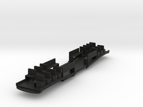
6. The floor orientation should have the side with the large air tank aligned to the side of the car which has the two small doorways (not the side with the large middle door). I applied my stirrups to the model with canopy glue without drilling, but the option to drill the body for them is certainly up to the modeler. I omitted one of the stirrups below one of the doors due to the trucks hitting it in turns.
7. Glaze the windows with some clear styrene and some canopy glue.
8. Enjoy being the coolest kid on the block.
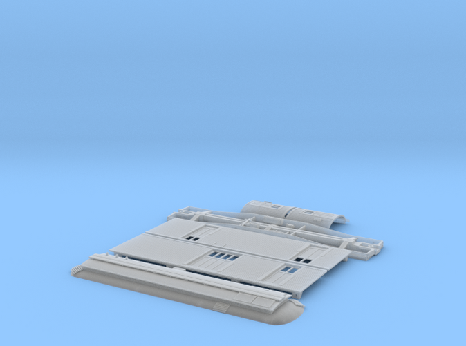
The prototype model shown is the basic "smooth fine detail plastic". You can really go all out and order it in "smoothest fine detail plastic", but for a wood-body car that would have lots of surface irregularity, it doesn't make a ton of sense to waste your money on it, but the option is yours.
Also note, my prototype here has one of the three insulators broken off the roof. Oops. Yours will have three like the prototype.
Please feel free to reach out with questions.
These were placed around the PE system to boost power in places where line voltage was found to be too low. They converted AC "city power" to 600 volts DC, and could be wired together in series to create the 1200 volts needed for the San Bernadino line. They were also used as a stand-in substation when permanent ones were downed for maintenance or repair.
This particular substation model is patterned after the last group of four portables built by the PE for the US Maritime Commission during WW2. They carried numbers 00184 to 00187. Originally they were lettered for the USMC but were later repainted and relettered for the PE, and then MTA. 00186 and 00187 lasted until the end of service in 1961 and could be seen along the Long Beach line, with many photographs taken of them in the area of Dominguez Junction.
Prototype photos shown below are for reference when painting and detailing this model and were scavenged from around the web and I did not keep good notes of from where they came. If they belong to you and you wish to have them credited or removed please reach out.
A shopping list to finish this model:
- .010 phosphor bronze wire for bending into hand-holds - available inexpensively through Tichy Train Group.
- Kadee 561 arch-bar trucks
- Kadee 148 whisker couplers and a scrap of flat plastic to create a lid for the coupler box (short shank may look better) - you can also just use a washer.
- 10 ea 1/4 inch 2-56 screws to attach the body to the floor and hold the couplers.
- Stirrup steps. I use A line stirrups but you can certainly bend your own.
- Two brake wheels - I scrounged my parts box and found a couple atlas RS3 brake wheels, but Kadee 2040 Ajax brake wheels would be appropriate for these.
- Paint - these were probaly box car red when assigned to the USMC, but wore pullman green with a tan roof in PE paint. I used scalecoat2 pullman green for the sides and TruColor flat tan for the roof. The floor and the scuff shields next to the door openings should be black.
- Decals - I used items from two microscale sets to decal the model shown. Set 87-589 has the fast freight shields. Set 87-563 was used for the lettering. I'm resourceful (read as cheap) and used individual yellow letters and numbers from an old almost-used-up 87-563 sheet I had around, but had to make the "B"s from a "P" and half of another letter to make the lower lobe of the B, as no Bs could be found anywhere on that sheet. That microscale sheet also has the Maritime Commision lettering if you choose to make yours a WW2 era model.
Assembly instructions:
1. Scrub all parts with un-diluted simple green and a tooth brush. I use a sonicare electric toothbrush. Rinse while scrubbing with the hottest water you can keep your hands in without getting scalded. Repeat for as long as you feel any waxy coating on the parts. This is critical for paint adhesion.
2. Tap the 8 holes in the mounting pads found on the back sides of the side walls with a 2-56 tap. Also tap the coupler pocket holes and the truck mounting holes with the 2-56 tap. Go easy and don't force it or you'll crack the model.
3. The hand holds and roof grabs have thier holes "pre-drilled" in the model to accept .010 wire. I use a Micro Mark handhold bending tool to bend my grabs in exact lengths so they look uniform. Make the legs a bit long to protrude into the carbody for easy and invisible gluing. I use CA (super glue) from the inside of the model to hold the grabs in place. If you want to buy one of these bending tools, there is a 10% discount available if you use the discount code "boulder" (works as of 10/1/20).
4. I paint the model in parts so the only masking required is to get the black on the scuff plates next to the doorways. You can paint it whole if that's your perogative, but I prefer the easy way.
5. Assemble the model. I glued the ends to the roof first. There are locator pegs to aid in alignment. I glued the pegs and the seam between them first, so that the outer corners of the ends could still be manipulated a bit to get the sides in good alignment. To get a sufficient amount of glue without going overboard, I put some CA in an old plastic water bottle cap, then use a toothpick to dab the glue onto the seams of the carbody from the inside. The green label Zap is my favorite for this. The red lable is a bit runny and tends to glue my fingers to the model.
Once the ends are in, the sides can be flexed slightly to get them to drop in between the ends, then push the alignment pegs into their holes with your fingernail from the inside. Apply the glue with a toothpick from the inside. The ends are identical and interchangeable, THE SIDES ARE NOT IDENTICAL - NOTE THE ALIGNMENT OF THE LADDERS TO THE ROOF MATS AND THE SUPPORTS FOR THE ELECTRICAL CONDUIT ON THE ROOF.
6. The floor orientation should have the side with the large air tank aligned to the side of the car which has the two small doorways (not the side with the large middle door). I applied my stirrups to the model with canopy glue without drilling, but the option to drill the body for them is certainly up to the modeler. I omitted one of the stirrups below one of the doors due to the trucks hitting it in turns.
7. Glaze the windows with some clear styrene and some canopy glue.
8. Enjoy being the coolest kid on the block.
The prototype model shown is the basic "smooth fine detail plastic". You can really go all out and order it in "smoothest fine detail plastic", but for a wood-body car that would have lots of surface irregularity, it doesn't make a ton of sense to waste your money on it, but the option is yours.
Also note, my prototype here has one of the three insulators broken off the roof. Oops. Yours will have three like the prototype.
Please feel free to reach out with questions.
Details
What's in the box:
Flat Portable Sub
Dimensions:
Success Rate:
First To try.
What's this?
Rating:
Mature audiences only.
