White Natural Versatile Plastic


SK-Chassis CFX
Made by
Print With Shapeways
 Choose Your Material
 Choose your color and finish
$54.43
Have a question about this product?
contact the designerYou must be logged in and verified to contact the designer.
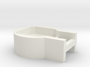
Product Description
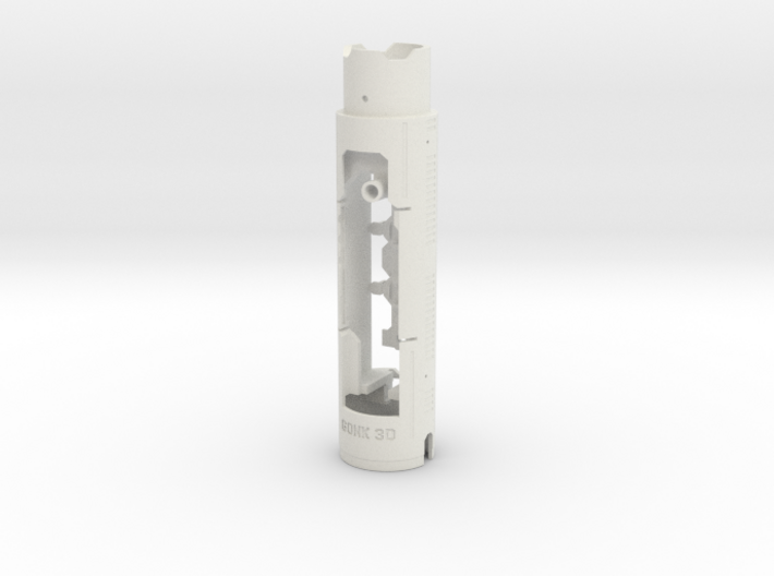
Chassis for Phoenix Props/7Chambers' SK saberhilt
(model updated:
-channel for battery push out
-more space for wires at solder pads for board +; -; speaker, (put wires under the board)
-additional securing holder for the board
This chassis system is made for CFX and 18650 battery holder.
Supported hardware:
-Plecter Lab's CFX
-28 to 32AWG wires or for switches, NPXL-dataline, speaker
-24AWG for board supply, 18 to 20AWG for neopixel-blade supply (recommending one 1 9 or 18 AWG wire per trace)
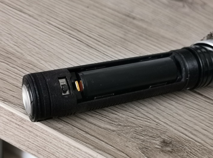
- keystone 18650 battery holder 1042P !!!cut off the snappers from the bottom side! Surface must be flush
-28mm bass speaker (2mm upper rim)
-killswitch 0.4VA
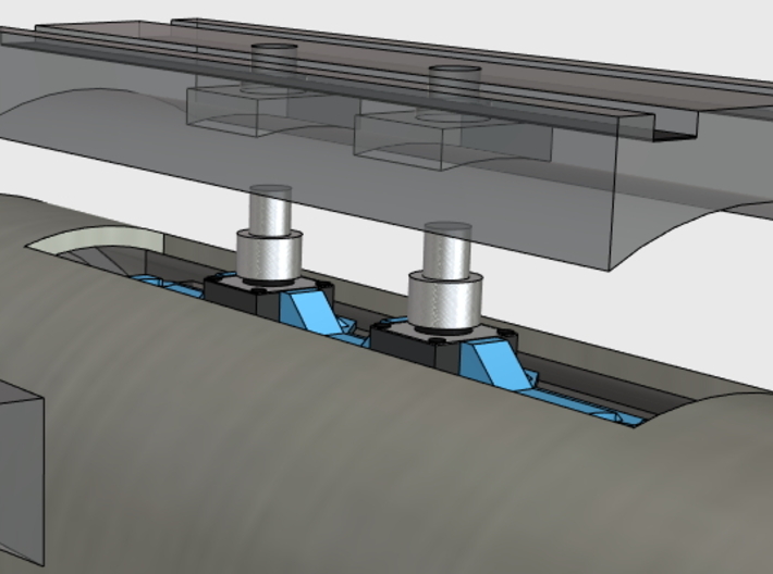
-standard tactiles (black 6x6mm 4.3mm high with pin) or flat metal tactiles (5x5mm, brass pin, may need additional isolation)
Feaures:
-crystal pixelholder included if neopixel setup is desired, takes different sizes
-includes switchholders for both types of switches stated above
Install instructions:
-exceed wires, resistors can be stored between battery holder and crystal chamber base
-the polycyrbonate crystal needs to be shortend if you want to put the pixelholder underneath
-chassis offers mounting holes exactly underneath the pre drilled holes in the big thread for the pommel section; tap a thread (M3, M4, similar inch threads), drill into the chassis' hole with the thread's core diameter, this will give a snug and tight fit when mounting with setscrews
Prototype install with neopixel worked best for me by assembling in the following order:
-drill and tap thread for retention holes for neopixeladapter/chassis
-prepare chassis assembly (inserting batteryholder)
-drill through given holes and tap setscrews inside to secure the holder
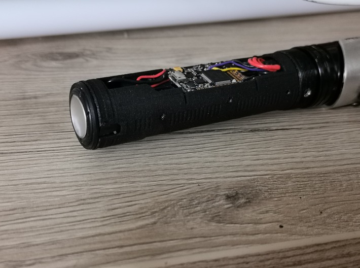
-place other wired components (speaker, killswitch, board
-keep wires as short as you can
-place prewired neopixel hiltside adapter at first, let heatsink cap away
-feed through switch area (visible wires through chamber also possible
-place prewired switch assembly
-feed al wires to opened bottom section
-screw on the controlbox and test If wires have enough space and can move a little
-wire a single pixel with 28awg or smaller and insert into crystal pixel holder
-place and secure the crystal pixel under the crystal
-carefully insert crystal assembly into the top section, make sure wires go well through the cutouts
-connect all wires, keep them short, store exceed wiring into the space between chamber and batteryholder
-wire board supplys from the downside
-isolate reveald connections (speaker contacts, ... )
(model updated:
-channel for battery push out
-more space for wires at solder pads for board +; -; speaker, (put wires under the board)
-additional securing holder for the board
This chassis system is made for CFX and 18650 battery holder.
Supported hardware:
-Plecter Lab's CFX
-28 to 32AWG wires or for switches, NPXL-dataline, speaker
-24AWG for board supply, 18 to 20AWG for neopixel-blade supply (recommending one 1 9 or 18 AWG wire per trace)
- keystone 18650 battery holder 1042P !!!cut off the snappers from the bottom side! Surface must be flush
-28mm bass speaker (2mm upper rim)
-killswitch 0.4VA
-standard tactiles (black 6x6mm 4.3mm high with pin) or flat metal tactiles (5x5mm, brass pin, may need additional isolation)
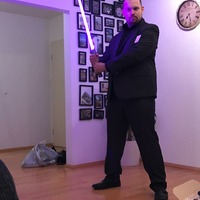
see picture at the end, I recommend to source somebody with a lathe to build switchplungers like those
Feaures:
-crystal pixelholder included if neopixel setup is desired, takes different sizes
-includes switchholders for both types of switches stated above
Install instructions:
-exceed wires, resistors can be stored between battery holder and crystal chamber base
-the polycyrbonate crystal needs to be shortend if you want to put the pixelholder underneath
-chassis offers mounting holes exactly underneath the pre drilled holes in the big thread for the pommel section; tap a thread (M3, M4, similar inch threads), drill into the chassis' hole with the thread's core diameter, this will give a snug and tight fit when mounting with setscrews
Prototype install with neopixel worked best for me by assembling in the following order:
-drill and tap thread for retention holes for neopixeladapter/chassis
-prepare chassis assembly (inserting batteryholder)
-drill through given holes and tap setscrews inside to secure the holder
-place other wired components (speaker, killswitch, board
-keep wires as short as you can
-place prewired neopixel hiltside adapter at first, let heatsink cap away
-feed through switch area (visible wires through chamber also possible
-place prewired switch assembly
-feed al wires to opened bottom section
-screw on the controlbox and test If wires have enough space and can move a little
-wire a single pixel with 28awg or smaller and insert into crystal pixel holder
-place and secure the crystal pixel under the crystal
-carefully insert crystal assembly into the top section, make sure wires go well through the cutouts
-connect all wires, keep them short, store exceed wiring into the space between chamber and batteryholder
-wire board supplys from the downside
-isolate reveald connections (speaker contacts, ... )
Details
What's in the box:
SK-Chassis-CfxPartCombo

Dimensions:
Success Rate:
First To try.
What's this?
Rating:
Mature audiences only.
More From This Shop
$9.00
$9.00