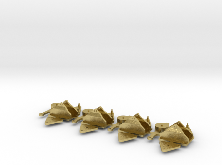
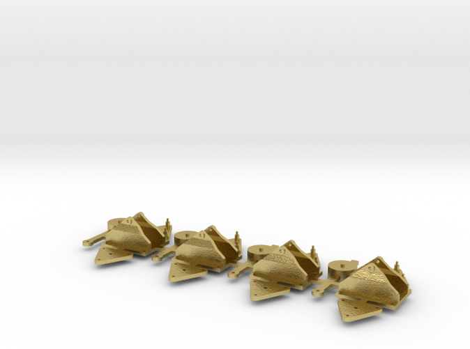
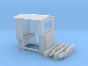
Levers as cast, before assembly


Set of 4 brass Throw over point levers
Made by
Print With Shapeways
 Choose Your Material
 Choose your color and finish
$23.15
Have a question about this product?
contact the designerYou must be logged in and verified to contact the designer.
Product Description
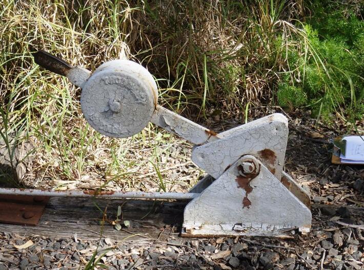
Set of four throw over point levers in 7mm O scale as used on cane tramways in Queensland. Will also work in 1/4" scale. The prototype is in use at the Illawarra Light Railway Museum in New South Wales. These levers are designed to give a small movement of the blades for a large movement of the lever. This makes them far less likely to accidently change position due to the shock of trains passing though the points. They will also work when the linkages are out of alignment.
Instructions:
(1) Remove the levers, triangular bodies and bases from the sprue and clean up.
(2) Use a drill open up the pivot holes in the levers, triangular bodies and bases to the size required for your pivot. I use a Peco track pin for the pivot as the pointed end makes it easier to line everything up during assembly.
(3) Use a drill to open up the alignment holes in the triangular bodies to take the small pins on the end of the spacers. Try to keep it a reasonably tight fit so both halves line up properly.
(4) Make the actuating linkage out of a piece of 0.5mm brass wire (not supplied). Form a loop that will go around one of the spacers.
(5) Paint everything before assembly. Clean any paint out of the holes.
(6) Fit the linkage over one of the spacers and glue both triangular bodiy pieces together. Be careful not to get glue on the linkage. Solder could be used but you will probably have to paint them after assembly.
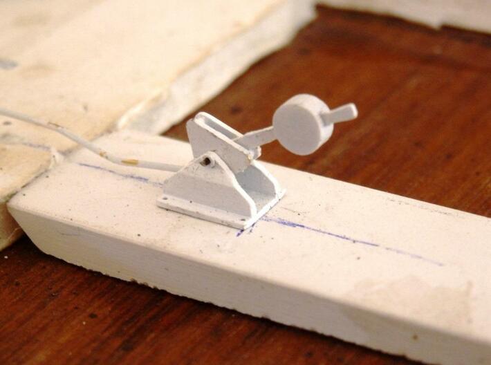
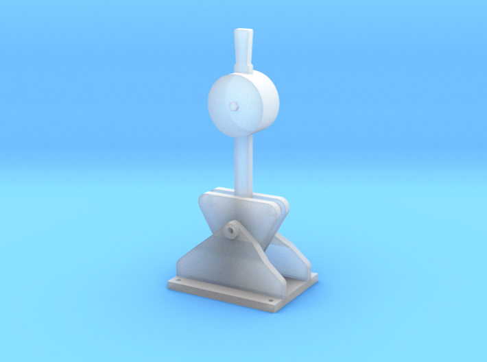
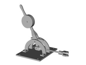
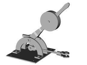
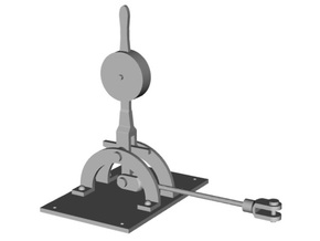
(7) Fit everything together by pushing the the pivot wire/pin through the bearing holes on the base, the centre of the triangular body and the lever. Fix the pivot to the base.
When connecting to your pointwork centre the blades to the halfway position (use small wedges of balsa to hold them), arrange the lever so that the top of the triangular body is horizontal and fix in place. This will give the lever an even throw in either direction. Don't worry if it is not perfect as plenty of these levers still worked well when wildly out of alignment.
The model levers were designed to be back driven by the point operating mechanism. The lever can be made to flip over to the other position by a sharp movement of the points. Depending on how your blades are pivoted the levers are robust enough to change the points. You may need to introduce some extra friction (piece of balsa rubbing under the linkage) to hold the blades in place. You still need a way of changing the frog polarity.
Instructions:
(1) Remove the levers, triangular bodies and bases from the sprue and clean up.
(2) Use a drill open up the pivot holes in the levers, triangular bodies and bases to the size required for your pivot. I use a Peco track pin for the pivot as the pointed end makes it easier to line everything up during assembly.
(3) Use a drill to open up the alignment holes in the triangular bodies to take the small pins on the end of the spacers. Try to keep it a reasonably tight fit so both halves line up properly.
(4) Make the actuating linkage out of a piece of 0.5mm brass wire (not supplied). Form a loop that will go around one of the spacers.
(5) Paint everything before assembly. Clean any paint out of the holes.
(6) Fit the linkage over one of the spacers and glue both triangular bodiy pieces together. Be careful not to get glue on the linkage. Solder could be used but you will probably have to paint them after assembly.
(7) Fit everything together by pushing the the pivot wire/pin through the bearing holes on the base, the centre of the triangular body and the lever. Fix the pivot to the base.
When connecting to your pointwork centre the blades to the halfway position (use small wedges of balsa to hold them), arrange the lever so that the top of the triangular body is horizontal and fix in place. This will give the lever an even throw in either direction. Don't worry if it is not perfect as plenty of these levers still worked well when wildly out of alignment.
The model levers were designed to be back driven by the point operating mechanism. The lever can be made to flip over to the other position by a sharp movement of the points. Depending on how your blades are pivoted the levers are robust enough to change the points. You may need to introduce some extra friction (piece of balsa rubbing under the linkage) to hold the blades in place. You still need a way of changing the frog polarity.
Details
What's in the box:
Croome Rd-Flat-3
Dimensions:
Success Rate:
First To try.
What's this?
Rating:
Mature audiences only.
