
Tan Fine Detail Plastic

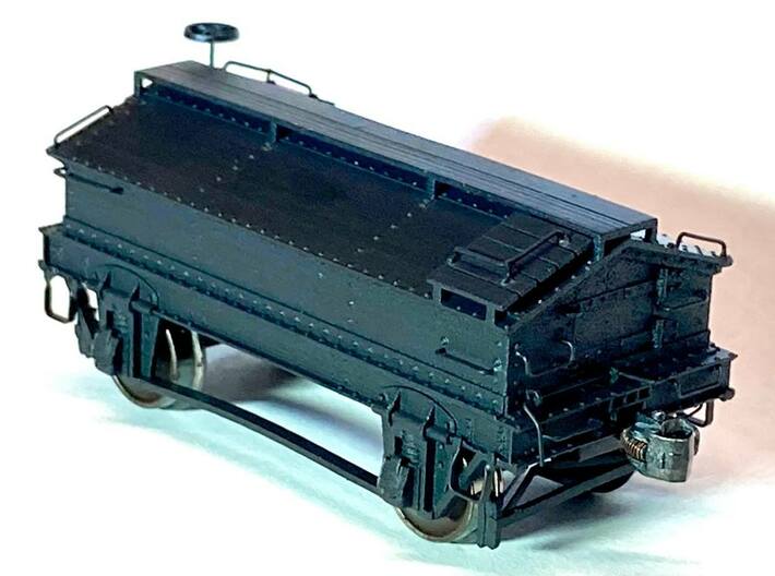


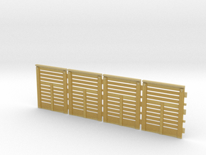
1916 Scale Test Car - HO Scale Model
Made by
Print With Shapeways
 Choose Your Material
 Choose your color and finish
$23.98
Have a question about this product?
contact the designerYou must be logged in and verified to contact the designer.
Product Description
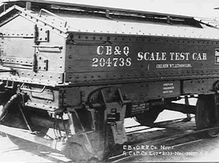
This is a one-piece model of a 1916 scale test car. The prototype is Chicago Burlington & Quincy 204738, built by ACF in 1916. Its purpose was to test the calibration of scales at loading points on the railroad. Many railroads owned scale test cars very similar to this one during the mid-20th century. The car is era-appropriate for about 1900 into the 1970s.
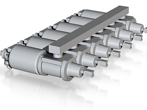
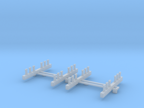
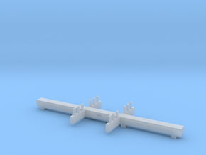
This car is intended to be something of a craftsman kit. The K-brake assembly and stirrups are molded on, but the modeler will need to supply and install cut levers and wire grabs (some are unusual lengths and will need to be bent from .010 or .0125 wire), brake staff, brake staff support if desired (.010x.030 brass strip), wheels, couplers, and weights.
Outside-hung brake beams are included, attached to the body of the car by sprue material, and may be built up using brass strip and hung using .0125 wire if desired. The car is designed for Intermountain or Accurail 36" wheels.
This model is a precision recreation of the prototype, which is preserved at the Illinois Railway Museum (www.irm.org). Paint and decals are not included (decals for this car are available from the Burlington Route Historical Society at https://www.burlingtonroute.org/store/index.php?category=models&button=Submit). An alternate one-piece version of this model with molded-on grab irons is available.
RECOMMENDED STEPS:
1. Wash car thoroughly with soap and water. Afterwards, remove brake beams and, if using, set aside.
2. Drill out grab iron holes with a #78 drill. There are eight holes on each end, four on each side, and a total of 10 on the roof of the car, plus the brake staff hole.
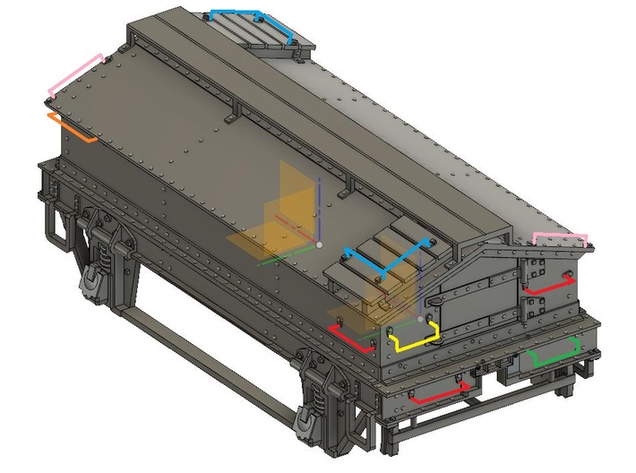
3. Bend grabs as needed from .010 or .0125 wire (see illustration; key is below) and install using CA. For grabs located on end sills, cut the inboard "legs" short so that they don't protrude into the coupler box area.
4. Invert car and install weight. Lead shot or small lead pellets are recommended, glued in place underneath body of car with CA.
5. Cut brake staff from .0125 or .015 wire to length and test fit but do not glue in place. If omitting the brake staff support stirrup, cut brake staff to a scale length of 4'6"; if including stirrup, cut staff to scale length of 6'3".
(If not installing outside-hung brake beams, skip to step 7.)
6. If installing brake beams, cut off sprue material, then bend .010x.030 brass strip as shown in illustration. Strip should extend between the brake shoes, making an angle over the rod in the center of the hanger. Drill out the four holes underneath the corners of the car, and bend .0125 wire so that the brake beams hang roughly even with the axle height and do not interfere with the wheels. The wire is affixed to the sides of the brake shoes with CA.
7. If installing cut levers, drill out holes for cut levers and install eye bolts and levers bent from .010 or .0125 wire. The handles at the outside ends of the cut levers have a 45-degree bend in the middle so that they hang over the end sill.
8. Cut and install .008 wire from retainer to the "deck" of the end sill at the B end.
9. Install couplers boxes. Kadee #158 couplers are recommended; swing is minimal but due to the construction of the car this should work. If wider coupler swing is needed, carefully file or slice the opening in the end sill to widen it out and use #156 long shank couplers. Coupler boxes can be installed using CA or brass #2 wood screws with #55 pilot hole.
10. If installing brake staff stirrup, bend .010x.030 brass strip into a hat section to create a stirrup 9" wide and 15" tall with short "ears". Glue in place centered underneath brake staff hole, using brake staff to help locate. Then glue brake staff and brake wheel in place.
11. Car is now ready to paint. Once painted, wheel sets may be snapped into place. Take care not to spread the pedestals apart any further than necessary.
Key to grab iron illustration (grab iron arrangement is same for A and B ends):
Red = 18" straight grabs (sides and ends)
Pink = 20" straight grabs (roof of car)
Blue = 18"x18" L-shaped grabs (roof of car)
Orange = 23" straight grabs (sides)
Yellow = 15" drop grabs (ends)
Green = 16" drop grabs (end sills)
This car is intended to be something of a craftsman kit. The K-brake assembly and stirrups are molded on, but the modeler will need to supply and install cut levers and wire grabs (some are unusual lengths and will need to be bent from .010 or .0125 wire), brake staff, brake staff support if desired (.010x.030 brass strip), wheels, couplers, and weights.
Outside-hung brake beams are included, attached to the body of the car by sprue material, and may be built up using brass strip and hung using .0125 wire if desired. The car is designed for Intermountain or Accurail 36" wheels.
This model is a precision recreation of the prototype, which is preserved at the Illinois Railway Museum (www.irm.org). Paint and decals are not included (decals for this car are available from the Burlington Route Historical Society at https://www.burlingtonroute.org/store/index.php?category=models&button=Submit). An alternate one-piece version of this model with molded-on grab irons is available.
RECOMMENDED STEPS:
1. Wash car thoroughly with soap and water. Afterwards, remove brake beams and, if using, set aside.
2. Drill out grab iron holes with a #78 drill. There are eight holes on each end, four on each side, and a total of 10 on the roof of the car, plus the brake staff hole.
3. Bend grabs as needed from .010 or .0125 wire (see illustration; key is below) and install using CA. For grabs located on end sills, cut the inboard "legs" short so that they don't protrude into the coupler box area.
4. Invert car and install weight. Lead shot or small lead pellets are recommended, glued in place underneath body of car with CA.
5. Cut brake staff from .0125 or .015 wire to length and test fit but do not glue in place. If omitting the brake staff support stirrup, cut brake staff to a scale length of 4'6"; if including stirrup, cut staff to scale length of 6'3".
(If not installing outside-hung brake beams, skip to step 7.)
6. If installing brake beams, cut off sprue material, then bend .010x.030 brass strip as shown in illustration. Strip should extend between the brake shoes, making an angle over the rod in the center of the hanger. Drill out the four holes underneath the corners of the car, and bend .0125 wire so that the brake beams hang roughly even with the axle height and do not interfere with the wheels. The wire is affixed to the sides of the brake shoes with CA.
7. If installing cut levers, drill out holes for cut levers and install eye bolts and levers bent from .010 or .0125 wire. The handles at the outside ends of the cut levers have a 45-degree bend in the middle so that they hang over the end sill.
8. Cut and install .008 wire from retainer to the "deck" of the end sill at the B end.
9. Install couplers boxes. Kadee #158 couplers are recommended; swing is minimal but due to the construction of the car this should work. If wider coupler swing is needed, carefully file or slice the opening in the end sill to widen it out and use #156 long shank couplers. Coupler boxes can be installed using CA or brass #2 wood screws with #55 pilot hole.
10. If installing brake staff stirrup, bend .010x.030 brass strip into a hat section to create a stirrup 9" wide and 15" tall with short "ears". Glue in place centered underneath brake staff hole, using brake staff to help locate. Then glue brake staff and brake wheel in place.
11. Car is now ready to paint. Once painted, wheel sets may be snapped into place. Take care not to spread the pedestals apart any further than necessary.
Key to grab iron illustration (grab iron arrangement is same for A and B ends):
Red = 18" straight grabs (sides and ends)
Pink = 20" straight grabs (roof of car)
Blue = 18"x18" L-shaped grabs (roof of car)
Orange = 23" straight grabs (sides)
Yellow = 15" drop grabs (ends)
Green = 16" drop grabs (end sills)
Details
What's in the box:
ScaleTestCar-WireGrabs-MoldedSteps

Dimensions:
Success Rate:
First To try.
What's this?
Rating:
Mature audiences only.