Yellow Processed Versatile Plastic

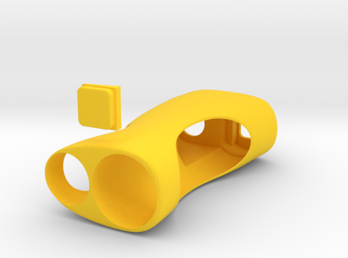
SquonkModX V3.1_V21700
Made by
Print With Shapeways
 Choose Your Material
 Choose your color and finish
$63.77
Have a question about this product?
contact the designerYou must be logged in and verified to contact the designer.
Product Description
20/21700 BATTERY VERSION
for 18650 see here
Dimensions: H97mm x W50mm x D30mm
Ver 3.1 V20/21700
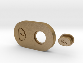
For Switchfet V2 –– You will also need the Switchfet Tray V1 Available Here.
For Switchfet V2.5 –– You will also need the Switchfet Tray V1.2 Available Here.
For Clickfet V1.0 – Your will also need the Clickfet Tray V1.2 Available Here.
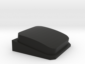
If you need another fire button in different colour you can order it here.
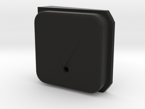
If you need a Clickfet Fire Button with hole for LED you can order it here.
Dimensions: H92mm x W46mm x D27mm
Notes: The battery tube opening is quite tight (for the right reasons) so you may need to brush it with some sandpaper to slide the s/s tube through. Also note that the tubes from MM are easily scratchable so take care when you put it in. Please refer to the images below on how to "construct" the electronics part. Putting it all together goes like this:
WHAT YOU NEED:
– MM510 with 22mm flat washer from ModMaker
– Switchfet V2 or V2.5 or Clickfet V1 from ModMaker
– MM 18650 Battery Tube from ModMaker (s/s or brass)
– 0.5mm² Ölflex Silcone Cable from ModMaker // or 1mm enamelled copper wire for tighter fit
– Shapeways Mod Print, Tray Print (see above)
Other things include a soldering iron + solder (of course), sand paper for fixing tolerances, RIT dye if printing white and want a custom colour, and some patience ;)
PLEASE REFER TO SWITCHFET/CLICKFET MANUAL FOR WIRING DIAGRAMS AND READ NECESSARY LITRATURE BEFORE PROCEEDING TO ENSURE SAFE INSTALLATION. KNOWLEDGE OF ELECTRONICS REQUIRED. NOT FOR BEGINNERS. SAFETY ALWAYS COMES FIRST!
STEP BY STEP:
Making of the Switchfet/Clickfet Tray and Wiring:
- Prepare the tray by testing whether it fits in the body and sanding down the circumference as necessary.
- Wire the Switchfet/Clickfet (all 3 points) leaving enough wire that you can cut later
- Lay the Switchfet/Clickfet into the tray sliding the wires (2 left (battery negative and 510 negative), 1 positive right) through the openings in the tray
- Push the switchfet/clickfet into the tray as much as you can
- Lay it on top of the top section of MM Battery Tube with positive ring connection facing right and negative facing left.
- Solder 510 negative from Switchfet/Clickfet to the negative ring of MM510
- Solder Switchfet/Clickfet Battery Negative to the MM Battery Tube Negative
- Solder the Switchfet/Clickfet Battery Positive to the Battery Tube Positive (very short wire)
- Solder the 510 Positive to the Battery Tube positive leaving enough wire (same as for MM510 negative) and on the other side solder to MM510 positive ring.
- Your electronics section is now complete.
Building the mod:
– Make sure that the MM battery tube fits, and brush down the opening with sandpaper as necessary.
– Make sure that the button has free movement in the opening – sand a little the opening if it needs it.
- Put the fire button in position in the mod (can be inserted later through the button hole by rotating 90* and at diagonal. The tray needs to be not in a end position for this to happen)
- Slide the electronics section into the mod by first pushing the positive and negative wires and rings into the 510 / bottle compartment. Keep in mind that you may need to bend the negative contact on the 510 ring in case you can't fit it all together.
- Pull back out the positive 510 connection into the battery compartment to make room for 510 fixing.
- Drop the 510 tightening but into position
- Insert 510 through the hole catching the negative ring from the electronics section.
– Tighten down the nut on the 510 by rotating the 510 - use a flat head screwdriver and jam it in between the body of the mod and the nut to hold it in place (you may need to do this from the battery compartment –– its quite tricky but doable)
– slide the positive ring onto 510 and position the final positive nut over the 510 and screw down –- all done through the battery compartment.
– Make sure there are no positive connections touching the negative, etc. This is quite important but common sense also I suppose.
– Slide the second part of the battery tube through the mod and rotate to screw onto the top part.
- Battery goes POSITIVE UP.
- Your mod is now complete.
I also recommend using MM 510 fixing kit otherwise you may lock up your atty in 510 as you are screwing down the 510. I did it without but maybe i was just lucky.
Making of photos here.
Q/A
Q: My battery tube is sticking out of my mod
A: Make sure that everything is tight in there and there is no room left between the electronics section and top of the inside of the mod (under the button).
Q: Yes, I’ve done that but its still sticking out
A: Your wiring was not tight enough, so you’ll need to shave off 1 or 1.5mm off the bottom of the button. Take everything out and try again. If its more than 1.5mm, there is something stuck and not allowing the fit.
Q: My battery tube is too recessed (my wiring is perfect!) and I want it flush with the bottom of the mod
A: You need to pad it somehow – try adding a spacer of some kind to underneath the button.
Q: Can I change the shell keeping all the electronics as they were
A: Yes. It was designed so it could be ported from shell to shell. 3D Printing is not very costly (not like C&C mill or hand work) so once you decide to change the mod design or colour you can do that w/o having to re-do your soldering, etc.
Need more help? Join the Facebook Group → https://www.facebook.com/groups/174399370002485/
Improvements planned for V3.1_V21700.1
- Opening for the battery tube is a bit slack so will make this a bit tighter. For now use kapton tape (or other) round the bottom of the tube to make it a friction fit if needed.
Need more help? Join the Facebook Group → https://www.facebook.com/groups/174399370002485/
for 18650 see here
Dimensions: H97mm x W50mm x D30mm
Ver 3.1 V20/21700
For Switchfet V2 –– You will also need the Switchfet Tray V1 Available Here.
For Switchfet V2.5 –– You will also need the Switchfet Tray V1.2 Available Here.
For Clickfet V1.0 – Your will also need the Clickfet Tray V1.2 Available Here.
If you need another fire button in different colour you can order it here.
If you need a Clickfet Fire Button with hole for LED you can order it here.
Dimensions: H92mm x W46mm x D27mm
Notes: The battery tube opening is quite tight (for the right reasons) so you may need to brush it with some sandpaper to slide the s/s tube through. Also note that the tubes from MM are easily scratchable so take care when you put it in. Please refer to the images below on how to "construct" the electronics part. Putting it all together goes like this:
WHAT YOU NEED:
– MM510 with 22mm flat washer from ModMaker
– Switchfet V2 or V2.5 or Clickfet V1 from ModMaker
– MM 18650 Battery Tube from ModMaker (s/s or brass)
– 0.5mm² Ölflex Silcone Cable from ModMaker // or 1mm enamelled copper wire for tighter fit
– Shapeways Mod Print, Tray Print (see above)
Other things include a soldering iron + solder (of course), sand paper for fixing tolerances, RIT dye if printing white and want a custom colour, and some patience ;)
PLEASE REFER TO SWITCHFET/CLICKFET MANUAL FOR WIRING DIAGRAMS AND READ NECESSARY LITRATURE BEFORE PROCEEDING TO ENSURE SAFE INSTALLATION. KNOWLEDGE OF ELECTRONICS REQUIRED. NOT FOR BEGINNERS. SAFETY ALWAYS COMES FIRST!
STEP BY STEP:
Making of the Switchfet/Clickfet Tray and Wiring:
- Prepare the tray by testing whether it fits in the body and sanding down the circumference as necessary.
- Wire the Switchfet/Clickfet (all 3 points) leaving enough wire that you can cut later
- Lay the Switchfet/Clickfet into the tray sliding the wires (2 left (battery negative and 510 negative), 1 positive right) through the openings in the tray
- Push the switchfet/clickfet into the tray as much as you can
- Lay it on top of the top section of MM Battery Tube with positive ring connection facing right and negative facing left.
- Solder 510 negative from Switchfet/Clickfet to the negative ring of MM510
- Solder Switchfet/Clickfet Battery Negative to the MM Battery Tube Negative
- Solder the Switchfet/Clickfet Battery Positive to the Battery Tube Positive (very short wire)
- Solder the 510 Positive to the Battery Tube positive leaving enough wire (same as for MM510 negative) and on the other side solder to MM510 positive ring.
- Your electronics section is now complete.
Building the mod:
– Make sure that the MM battery tube fits, and brush down the opening with sandpaper as necessary.
– Make sure that the button has free movement in the opening – sand a little the opening if it needs it.
- Put the fire button in position in the mod (can be inserted later through the button hole by rotating 90* and at diagonal. The tray needs to be not in a end position for this to happen)
- Slide the electronics section into the mod by first pushing the positive and negative wires and rings into the 510 / bottle compartment. Keep in mind that you may need to bend the negative contact on the 510 ring in case you can't fit it all together.
- Pull back out the positive 510 connection into the battery compartment to make room for 510 fixing.
- Drop the 510 tightening but into position
- Insert 510 through the hole catching the negative ring from the electronics section.
– Tighten down the nut on the 510 by rotating the 510 - use a flat head screwdriver and jam it in between the body of the mod and the nut to hold it in place (you may need to do this from the battery compartment –– its quite tricky but doable)
– slide the positive ring onto 510 and position the final positive nut over the 510 and screw down –- all done through the battery compartment.
– Make sure there are no positive connections touching the negative, etc. This is quite important but common sense also I suppose.
– Slide the second part of the battery tube through the mod and rotate to screw onto the top part.
- Battery goes POSITIVE UP.
- Your mod is now complete.
I also recommend using MM 510 fixing kit otherwise you may lock up your atty in 510 as you are screwing down the 510. I did it without but maybe i was just lucky.
Making of photos here.
Q/A
Q: My battery tube is sticking out of my mod
A: Make sure that everything is tight in there and there is no room left between the electronics section and top of the inside of the mod (under the button).
Q: Yes, I’ve done that but its still sticking out
A: Your wiring was not tight enough, so you’ll need to shave off 1 or 1.5mm off the bottom of the button. Take everything out and try again. If its more than 1.5mm, there is something stuck and not allowing the fit.
Q: My battery tube is too recessed (my wiring is perfect!) and I want it flush with the bottom of the mod
A: You need to pad it somehow – try adding a spacer of some kind to underneath the button.
Q: Can I change the shell keeping all the electronics as they were
A: Yes. It was designed so it could be ported from shell to shell. 3D Printing is not very costly (not like C&C mill or hand work) so once you decide to change the mod design or colour you can do that w/o having to re-do your soldering, etc.
Need more help? Join the Facebook Group → https://www.facebook.com/groups/174399370002485/
Improvements planned for V3.1_V21700.1
- Opening for the battery tube is a bit slack so will make this a bit tighter. For now use kapton tape (or other) round the bottom of the tube to make it a friction fit if needed.
Need more help? Join the Facebook Group → https://www.facebook.com/groups/174399370002485/
Details
What's in the box:
SquonkModX V3.1_V21700

Dimensions:
Success Rate:
First To try.
What's this?
Rating:
Mature audiences only.

More From This Shop
$35.00