


Containerauflieger HLS200.78/TK Transport
Made by
Print With Shapeways
 Choose Your Material
 Choose your color and finish
$26.21
Have a question about this product?
contact the designerYou must be logged in and verified to contact the designer.
Product Description
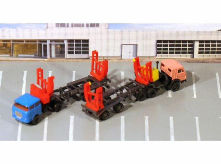
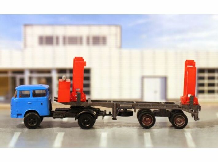
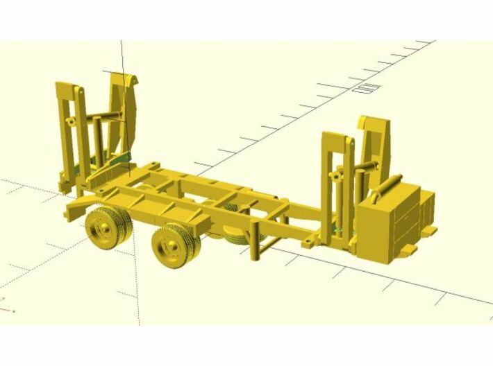
DE: Dies ist das Modell des Containeraufliegers HLS 200.78/TK, wie er in der DDR in den 70er und 80er Jahren verwendet wurde. Diese Auflieger konnten einen 20-Fuß-Container ohne Hilfe eines Kranes aufnehmen und absetzen. Das konkrete Modell zeigt die eingeklappten Liftarme in Transportstellung. Eine Variante dieses Modells mit den Liftarmen in ausgeklappter Stellung zum Be- und Entladen eines Containers ist ebenfalls in diesem Shop zu haben. Es handelt sich um ein statisches Modell. Es wird unmontiert und unlackiert sowie ohne Decals, ohne Zugmaschine und ohne Container geliefert. Eventuell in den Bildern zu sehende weitere Modelle dienen nur der Illustration.
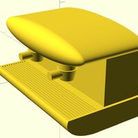
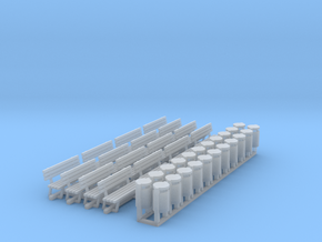
Bauanleitung: Trennen Sie die Teile mit einem scharfen Skalpell vom Träger. Lackieren Sie das Chassis schwarz oder anthrazit, die Räder und Stützen schwarz, Umlenkrollen (die Teile, die wie dreieckige Prismen mit abgerundeten Ecken aussehen) und die Containerhaken (L-förmige Teile) gelb, das Abgasrohr und die offen liegenden Hubzylinder an den Liftarmen silbern und die Liftarme sowie den Maschinenkasten in den Farben des gewünschten Vorbilds.
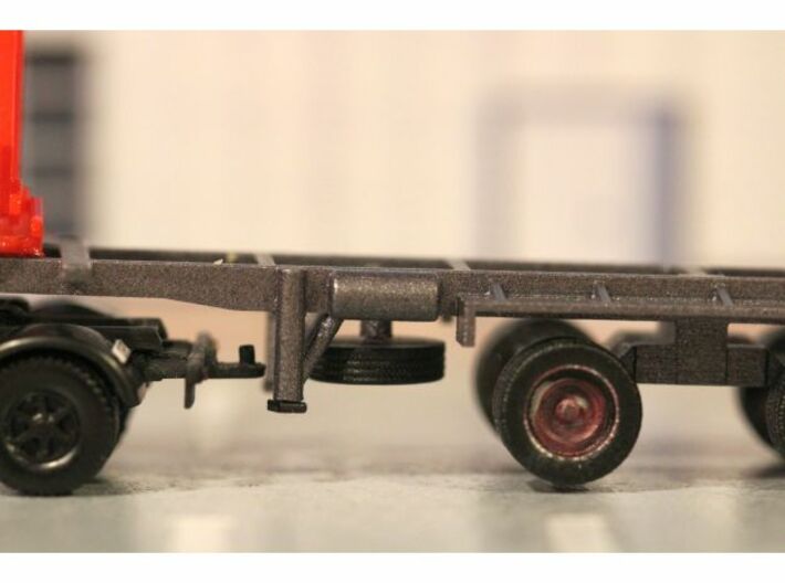
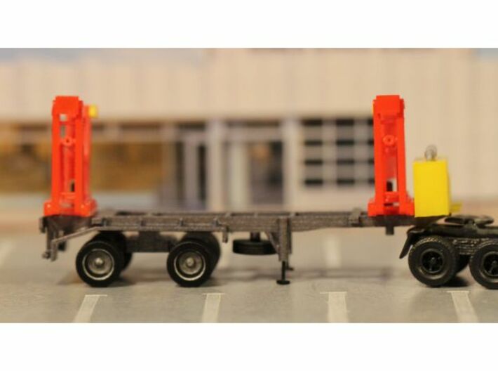
Kleben Sie die Umlenkrollen an die Stifte am oberen Ende des Liftarms. Positionieren Sie den hinteren Liftarm am Rahmenende. Die Führungen sollten schwergängig zwischen den Rahmenträgern einrasten. Wenn dies nicht der Fall ist, von den Führungen ein wenig Material wegfeilen. Wenn der Arm passt, mit Klebstoff fixieren. Achtung: Die Liftarme sind spiegelsymmetrisch, die Umlenkrollen müssen bei montierten Liftarmen nach innen weisen. Die Position des vorderen Liftarms bestimmen Sie am besten, indem Sie einen 20-Fuß-Modellcontainer auf dem Rahmen platzieren. Montieren Sie diesen in gleicher Weise wie den hinteren. Montieren Sie den Maschinenkasten bündig vor dem vorderen Liftarm und befestigen Sie das Abgasrohr auf diesem. Bohren Sie die Achsführungen am Rahmen vorsichtig mit einem Bohrer auf, der Ihrem gewählten Achsmaterial entspricht. Bohren Sie die Führungen der Stützen zunächst mit einem 0.6-Millimeter-Bohrer und anschließend mit einem 0.7-mm-Bohrer auf. Die Stützen werden nur eingesteckt und bleiben so beweglich. Es sollte aber genug Reibung vorhanden sein, dass diese nicht herausfallen. Schneiden Sie Achsen passend zu. Bohren Sie an den Rädern die Achsführungen auf das gewünschte Maß auf. Stecken Sie die Achsen in die Achsführungen des Rahmens, geben Sie einen kleinen Tropfen Klebstoff in die Achsführungen der Räder und stecken Sie diese auf die Achsen auf. Auf diese Weise sollten die Räder drehbar bleiben. Befestigen Sie das Reserverad am Befestigungspunkt unterhalb des Rahmens. Detailieren Sie das Heck mit einem Kennzeichen aus Papier und indem Sie die Rückleuchten mit Permanentmarker auftragen.
EN: This is the model of a self-loading container trailer HLS 200.78/TK which was made and used in the GDR in the 1970s and 1980s. This trailer could load and unload a 20 foot container without the help of a crane. This particular model represents the state of closed liftarms during transport. There is a version of this model in this shop which represents the state during loading and unloading. It is a static model, i.e. the lift arms cannot be moved. It is delivered as a kit, unpainted, without decals, tractor and container. Images with several vehicles or buildings in them merely serve as illustrations in which settings the model could be used.
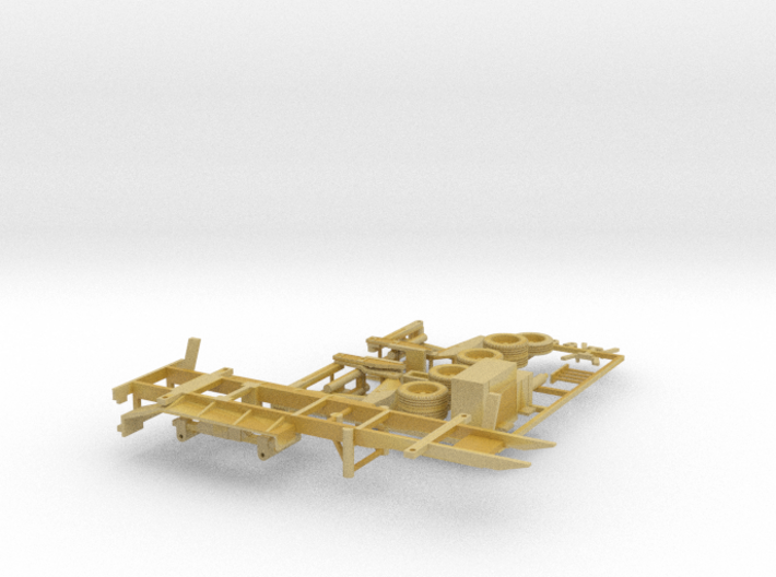
Building instructions: Please remove all parts carefully from the sprue or separate them from each other with a scalpel.Carefully clean an decrease the surfaces, suggested method is by bathing them in unscented detergent for 24 hours, then thoroughly rinsing them and lightly brushing them with a toothbrush. Paint the chassis black or anthracite, wheels and hydraulic supports black, pulleys (the triangular parts with rounded edges) and container clamps (L-shaped parts) yellow, the exhaust pipe and the visible part of the lift cylinders silver, and the lift arms and the engine cover in the colours of your desired prototype.
Glue the pulleys to the pins at the upper end of the lift arms. Position the rear lift arm at the end of the chassis. The guide rails at the bottom of the lift arm should tightly fit in between the frame of the chassis. If this is not the case file off some material from the guide rails. When the arm fits glue it to the frame. Attention: The lift arms are mirror images of each other, the pulleys must point in the direction of the other arm. The position of the front lift arm is best found by placing the model of a 20 foot container on the chassis. Mount the front lift arm in the same way as the rear lift arm. Glue the engine cover to the frame right in front of the front lift arm and glue the exhaust pipe to the top of it. Bore out the axle bearings in the frame very carefully with a diameter that fits your chosen brass axle diameter which should be between 0.5 and 0.8 mm. Bore out the cylinders of the hydraulic supports first with a 0.6 mm drill, then with a 0.7 mm drill. The supports will only be shoved into the cylinder (not glued) and remain moveable. There should be enough friction for them not to fall off. Cut axles from round brass material. Bore out the axle bearings on the wheels, add a tiny drop of glue to them and push the axles through the bearings on the frame. Then stick the wheels onto the ends of the axles. Thus, the wheels should be able to turn. Attach the spare wheel to the pin underneath the frame. Detail the rear end by painting the rear lights with permanent marker and creating registration plates out of paper.
Bauanleitung: Trennen Sie die Teile mit einem scharfen Skalpell vom Träger. Lackieren Sie das Chassis schwarz oder anthrazit, die Räder und Stützen schwarz, Umlenkrollen (die Teile, die wie dreieckige Prismen mit abgerundeten Ecken aussehen) und die Containerhaken (L-förmige Teile) gelb, das Abgasrohr und die offen liegenden Hubzylinder an den Liftarmen silbern und die Liftarme sowie den Maschinenkasten in den Farben des gewünschten Vorbilds.
Kleben Sie die Umlenkrollen an die Stifte am oberen Ende des Liftarms. Positionieren Sie den hinteren Liftarm am Rahmenende. Die Führungen sollten schwergängig zwischen den Rahmenträgern einrasten. Wenn dies nicht der Fall ist, von den Führungen ein wenig Material wegfeilen. Wenn der Arm passt, mit Klebstoff fixieren. Achtung: Die Liftarme sind spiegelsymmetrisch, die Umlenkrollen müssen bei montierten Liftarmen nach innen weisen. Die Position des vorderen Liftarms bestimmen Sie am besten, indem Sie einen 20-Fuß-Modellcontainer auf dem Rahmen platzieren. Montieren Sie diesen in gleicher Weise wie den hinteren. Montieren Sie den Maschinenkasten bündig vor dem vorderen Liftarm und befestigen Sie das Abgasrohr auf diesem. Bohren Sie die Achsführungen am Rahmen vorsichtig mit einem Bohrer auf, der Ihrem gewählten Achsmaterial entspricht. Bohren Sie die Führungen der Stützen zunächst mit einem 0.6-Millimeter-Bohrer und anschließend mit einem 0.7-mm-Bohrer auf. Die Stützen werden nur eingesteckt und bleiben so beweglich. Es sollte aber genug Reibung vorhanden sein, dass diese nicht herausfallen. Schneiden Sie Achsen passend zu. Bohren Sie an den Rädern die Achsführungen auf das gewünschte Maß auf. Stecken Sie die Achsen in die Achsführungen des Rahmens, geben Sie einen kleinen Tropfen Klebstoff in die Achsführungen der Räder und stecken Sie diese auf die Achsen auf. Auf diese Weise sollten die Räder drehbar bleiben. Befestigen Sie das Reserverad am Befestigungspunkt unterhalb des Rahmens. Detailieren Sie das Heck mit einem Kennzeichen aus Papier und indem Sie die Rückleuchten mit Permanentmarker auftragen.
EN: This is the model of a self-loading container trailer HLS 200.78/TK which was made and used in the GDR in the 1970s and 1980s. This trailer could load and unload a 20 foot container without the help of a crane. This particular model represents the state of closed liftarms during transport. There is a version of this model in this shop which represents the state during loading and unloading. It is a static model, i.e. the lift arms cannot be moved. It is delivered as a kit, unpainted, without decals, tractor and container. Images with several vehicles or buildings in them merely serve as illustrations in which settings the model could be used.
Building instructions: Please remove all parts carefully from the sprue or separate them from each other with a scalpel.Carefully clean an decrease the surfaces, suggested method is by bathing them in unscented detergent for 24 hours, then thoroughly rinsing them and lightly brushing them with a toothbrush. Paint the chassis black or anthracite, wheels and hydraulic supports black, pulleys (the triangular parts with rounded edges) and container clamps (L-shaped parts) yellow, the exhaust pipe and the visible part of the lift cylinders silver, and the lift arms and the engine cover in the colours of your desired prototype.
Glue the pulleys to the pins at the upper end of the lift arms. Position the rear lift arm at the end of the chassis. The guide rails at the bottom of the lift arm should tightly fit in between the frame of the chassis. If this is not the case file off some material from the guide rails. When the arm fits glue it to the frame. Attention: The lift arms are mirror images of each other, the pulleys must point in the direction of the other arm. The position of the front lift arm is best found by placing the model of a 20 foot container on the chassis. Mount the front lift arm in the same way as the rear lift arm. Glue the engine cover to the frame right in front of the front lift arm and glue the exhaust pipe to the top of it. Bore out the axle bearings in the frame very carefully with a diameter that fits your chosen brass axle diameter which should be between 0.5 and 0.8 mm. Bore out the cylinders of the hydraulic supports first with a 0.6 mm drill, then with a 0.7 mm drill. The supports will only be shoved into the cylinder (not glued) and remain moveable. There should be enough friction for them not to fall off. Cut axles from round brass material. Bore out the axle bearings on the wheels, add a tiny drop of glue to them and push the axles through the bearings on the frame. Then stick the wheels onto the ends of the axles. Thus, the wheels should be able to turn. Attach the spare wheel to the pin underneath the frame. Detail the rear end by painting the rear lights with permanent marker and creating registration plates out of paper.
Details
What's in the box:
hls200-78tk_bausatz_neu

Dimensions:
Success Rate:
First To try.
What's this?
Rating:
Mature audiences only.


