

Material Info
About
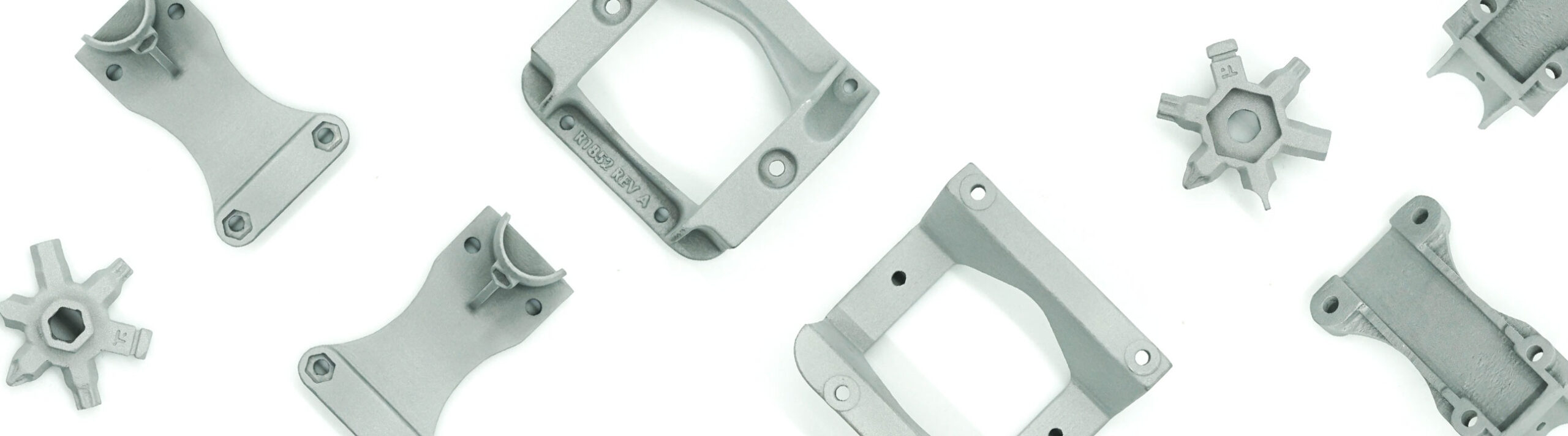
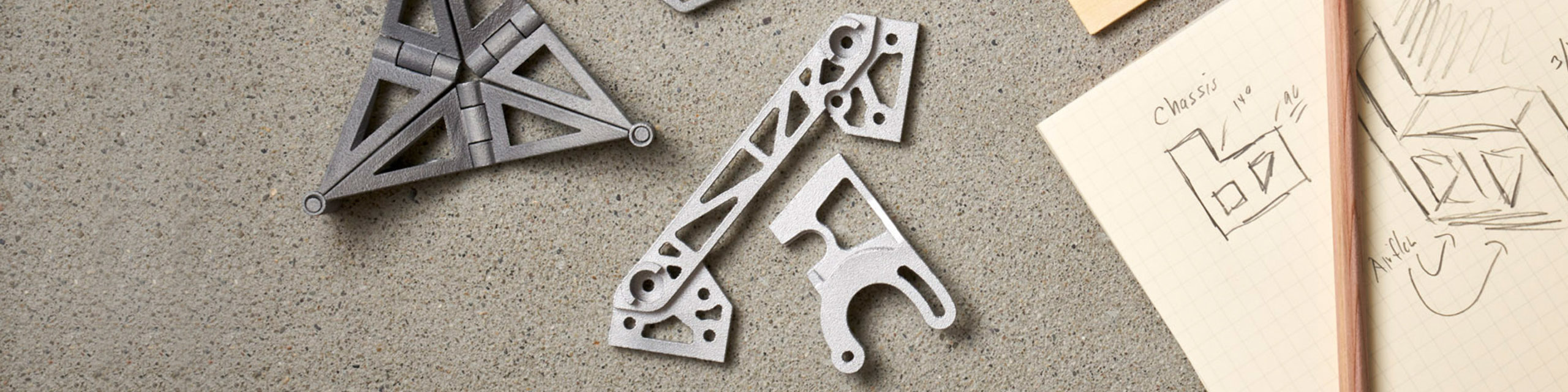
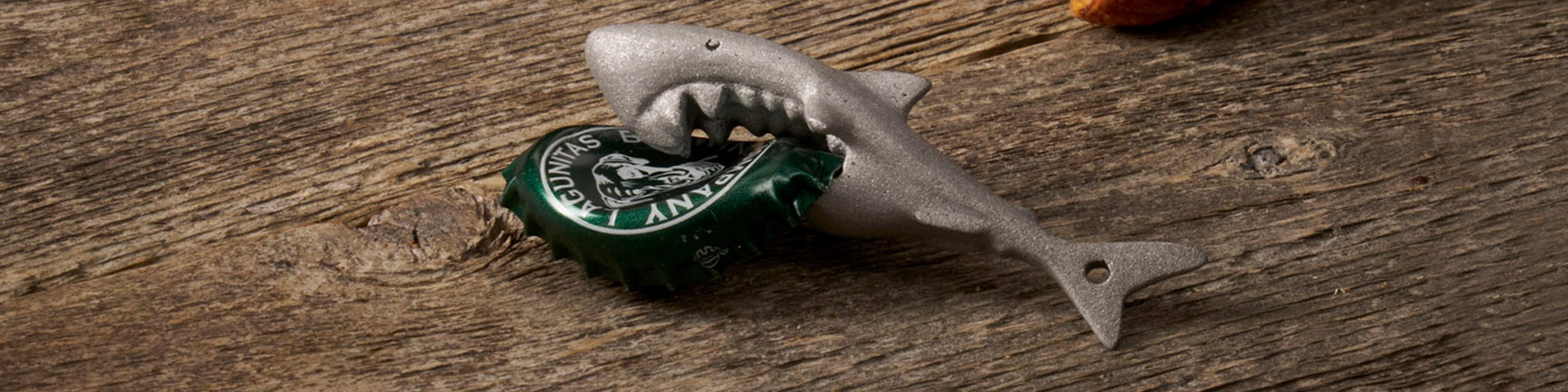
Aluminum 3D printing material is both lightweight and strong, recommended for functional parts requiring durability, stiffness, and high accuracy. Aluminum 3D printing relies on Selective Laser Melting (SLM) technology. Aluminum or 3D printed aluminum (alloy AlSi10Mg, 10% Silicon 0.5% Mg) offers great corrosion resistance, making it an ideal material for outdoor applications, also providing high electrical and thermal conductivity. 3D printed aluminum can be machined, milled and tapped too. More information about this material can be found in our Here.
Color & Finishes

In certain areas the surface of 3D printed aluminum can be slightly rougher than others, due to where supports were added.
Technical Documents
Material Properties
Description
Design Guidelines
Bounding Box
Maximum Bounding Box
250 x 250 x 200 mm
Minimum Bounding Box
X + Y + Z > 30 mm
The bounding box is a 3D imaginary outline of a box that encloses the smallest area occupied by your model. Your model must be within the minimum and maximum bounding box sizes. If the size of the model is close to the maximum bounding box, then the printing orientation will be restricted.
Walls
0.8 mm
A supported wall is connected at least on two sides of the wall, while an unsupported wall is connected only on one side of the wall. Walls that do not meet the minimum requirements may not survive printing and cleaning processes. Additionally, models may still be rejected based on the wall geometry of the model. Please consider the size of your model and reinforce the walls or add support structures as needed as minimum guidelines will not always be adequate for large models.
Wires
1.5 mm
1.5 mm
A wire is a circular, rectangular or even triangular feature that is thinner in its unconnected directions than its length. A supported wire is connected at least on two sides of the model, while an unsupported wire is connected on one side of the model. Wires that do not meet the minimum requirements may not survive printing and cleaning processes. Additionally, models may still be rejected based on the wire geometry of the model. Please consider the size of your model and reinforce the wires or add support structures as needed as minimum guidelines will not always be adequate for large models.
Details
0.4 mm high & wide
0.5 mm high & 0.8 mm wide for text
0.4 mm high & wide
0.5 mm high & 0.8 mm wide for text
For text, the ratio between width and depth, should be 1:1 and sans-serif fonts are preferred for line weight consistency.
Escape Holes
4.0 mm
2.0 mm
Escape holes are necessary to empty the support material of a hollow model. Two escape holes at the opposite ends of the model is optimal for the support removal process. Please consider the size of your model and make the escape holes bigger or add more escape holes as needed as minimum guidelines will not always be adequate for large models.
Clearance
0.6 mm
Clearance is the space between two individual parts in a model. If the space among the individual parts do not meet the minimum clearance, then parts can fuse together or can be difficult to clean. This is important for movable pieces like hinges, gears, etc.
Interlocking & Enclosed Parts
Interlocking
Yes
Enclosed
No
Parts in File
1 per model
Accuracy
± 0.2 mm for 3D printed aluminum products under 10mm in all dimensions, ± 1.5% for 3D printed aluminum products over 10 mm in any dimension.