How do you create mathematical models?

Discussion in 'Design and Modeling' started by 394883_deleted, Jan 13, 2015.

  1. Luxxeon3D
    Luxxeon3D Well-Known Member
    Also, please note that the blend file I uploaded is by no means perfect. There's still a problem with how the dual instances of the Solidify modifier is deforming the surface of the mesh. Also, we are missing one very crucial step: smoothing the vertices of the mesh; a process which would occur after the squeeze effect, and before the Subdivision Surface modifier is applied. I think the lack of this step may be the reason we have overlapping faces in the Solidify process.
     
    Last edited: Jun 15, 2015
  2. Thanx, I'll have a look.

    On the lighter / brighter side, I just sent off
    my floral ball to print.

    I should be getting it near the end of June.

    (It shipped, June 17. Arrived, June 20).

    No problems up to this point. Printability
    checks passed. Currently in production.

    As promised:

    printed_shapeways.JPG

    It's about 45mm which is a little less than 2 in in size.

    And about $ 15 to print (white plastic being the cheapest material)
    See the other image for details (With S+H - closer to $ 20+)

    It would probably pass muster at larger sizes, or other materials as well.
    And an increase in cost to go with it.


    Attached Files:

    Last edited: Jun 20, 2015
  3. JACANT
    JACANT Well-Known Member
    The RSDoc file, is the default file for DesignSpark Mechanical.

    DSM does not have a 'Squeeze' function or any subdivision modifiers.

    The disjointed files may be from the DSM file when saved as Stl. In the DSM file there is the solid model your original mesh file that was saved from Blender as a Dae file, opened in Sketchup, saved as a Skp file and opened in DSM then I copied the surfaces and edges to create the solid model. DSM can read and write Skp files.

    When exported from DSM as an Stl file there are options to alter the resolution with controls for the deviation and the angle of faces to give a true smooth model.

    DSM is a more exact mechanical drawing program.

    Have you ever tried Topmod? http://tinyurl.com/cblc54u
     
    Last edited: Jul 14, 2015
  4. The attached image below should answer your question.

    The other image (merged.png) is a side by side comparison of my object in Blender
    and your object from DesignSpark in Blender. The Blender object is simple. A Hexagon
    of six sides, straight lines, minimal vertices and edges, and overall topology. Your DesignSpark
    model is a multitude of unnecessary vertices making any changes, such as smoothing, unnecesarily
    cumbersome. Not to mention any editing for simplification.

    Not sure why that is. Google's Sketchup has comparable problems.

    It pretty much dictates that whatever you start in either Sketchup or DesignSpark (or some other
    programs for that matter), you're bound to finish in the same program. It's just easier than trying
    to port the model over to a different program. Just as it's problematic going from Sketchup / DesignSpark
    to Blender, the converse is also likely problematic, that of going from Blender to Sketchup / DesignSpark
    or other CAD / CAE programs as well. It's not a one way problem.

    Just thought this would be more helpful than just saying "it's not working." With a, hopefully clearer
    example of what "not working" means.
     

    Attached Files:

    Last edited: Jun 18, 2015
  5. I was just tinkering around with Blender and stumbled across the nurbs menu under Add / Surface - Shift-A.

    Comparing that to this, the cylinder bend, under 3DSMax in this video:

    3ds Max and Blender comparisons Using Modifiers...
    https://www.youtube.com/watch?v=hT0PH2F0oEE

    and converting Mesh to Nurbs here:

    Convert Mesh models into Nurb Models
    http://www.npowersoftware.com/nurbs/scanned_mesh_to_nurbs_np ower_software/scanned_mesh_to_nurbs_npower_software.html

    There doesn't seem to be a way or an EASY way to do this in Blender (understandable due to the complexity of some Mesh):

    Blender - Mesh to Nurbs (Discussion)
    http://blenderartists.org/forum/showthread.php?134614-Mesh-t o-Nurbs

    It seems to be predicated on HOW 3DSMax (perhaps other high end 3D modeling tools) work with objects. Perhaps helping to
    explain why there's no smoothing tool (yet) in Blender. Much like the reasons why it's easier to do precision work in CAD / CAE
    than it is in Blender. It's just a reflection of what they are designed for and intended to do. Perhaps an analogy might be why architects
    design homes rather than sculptors or glassblowers. They simply bring very different skill sets, tools, and talents to the task.

    Make sense?

    Perhaps a nurb version of this model might be more malleable towards the end result than mesh as it's understood in Blender. Perhaps
    the difference in how 3DSMax works with objects helps to explain why the smoothing tool is possible in 3DSMax rather than Blender.

    As the joke goes, you don't get down from an Elephant, you get "Down" from a duck (How do you get down from an elephant?). Smoothing,
    at this point, is just, unless someone knows different, something more easily, readily done in 3DSMax (for now).

    Same thing for Voronoi in Rhino and Grasshopper (or is Grasshopper an addon for Rhino - I forget). Just as I'm sure Blender has some built
    in tasks and methods that just make it easier to do some things in Blender vs other tools.

    It all, seems to me, comes down to knowing the strengths and weaknesses of respective tools and understanding that, in that regard, using
    each for it's respective strengths is better than the infighting regarding which TOOL is BETTER.
     
    Last edited: Jun 18, 2015
  6. Luxxeon, Jacant, others here, you might like, if you didn't already know about, this:

    https://www.craftsmanspace.com/free-3d-models/topological-mes h-modeling-examples-converted-to-nurbs-surfaces.html

    Looks like it's got both, as I understand it, popular streams of modeling covered, poly as well as CAD/CAE.

    Speaking of which, here's what I've got.

    Blender
    Inkscape
    Gimp
    Pinta
    HeeksCAD
    OpenScad
    FreeCad
    Wings3D
    ArtofIllusion
    MeshLab
    Netfabb(Basis)
    Google Sketchup (2015 - Free Version)
    Raspberry Pi (Mathematica)
    Wolfram CDF Player
    TopMod

    and through Shapeways -

    TinkerCAD

    No mastery in ANY of them.

    But, as I've mentioned, they serve their
    purposes. The CAD tools as a conduit
    between CAD (IGES, STEP, DWG et.al)
    and the tool I use the most for 3D
    modeling: Blender.

    FYI.

    Enjoy.


    Last edited: Jun 18, 2015
  7. Luxxeon3D
    Luxxeon3D Well-Known Member
    Unkerjay, I'll have to review some of those links when I have some more time, but I could touch briefly on some points regarding Nurbs and Polygon modeling. I personally gravitated to subdivision polygon modeling over Nurbs many years ago, based on a few factors of the modeling process in comparison between the two types of object creation. Nurbs stands for Non-Uniform Rational B-Splines. A good read about the differences of each is laid out here:

    https://seraphinacorazza.wordpress.com/2012/12/28/modeling-t echniques-differences-between-nurbs-and-polygon-modelling-ne w-york-city-rooftop-3d-architecture-project-research/

    One important factor to remember is that either method of creation can be used to build any structure. It's simply a matter of the ultimate needs of the artist using the software in the end. Nurbs are more commonly used for architectural and industrial modeling needs, because the surfaces are usually much smoother to start with, and it's easier to remain perfectly accurate, and match precision drawing lines with Nurbs curves. It's like comparing the usefulness of Vector line drawings to pixel-based raster paint software, in other digital design mediums. Nurbs also work much better with booleans than polygons do, making Nurbs ideal for solid modeling objectives.

    That said, I prefer to model in polygons, by choice. One big reason is that I feel polygonal based objects are easier to create, and manipulate, while allowing the user access to a far more simplified surface as the base (primitive). Complex organic objects are often more controllable with subdivision polygons, as you have access to the simple base mesh, and the results can be used for a larger variety of purposes. Overall, the two platforms of creation can often be used interchangeably as you've pointed out, providing a wide range of possibilities. I believe any shape can be achieved through either Nurbs or Polygons, and that has been proven already in many cases.

    I used to use Topmod years ago, well before I moved on to 3dsmax, and it was a very clever software. It was one of the very first packages I learned to use in the world of 3D. The limitations of it became evident after a while, however, and modeling in it was fairly slow going; although easy to learn. I then moved to Wings3d, which I found far more robust, while still maintaining manifold objects in the modeling environment. When I switched later to 3dsmax, I was a bit unnerved by the lack of "solid" modeling funcitonality, but soon found it to be even more versatile than the previous two packages, in the long run.

    Blender does have vertex smoothing, which is very similar to the relax option in 3dsmax. There are some differences in the behavior of some of the modifiers, however, that makes a difference in how some of the objects are created in either application. Blender does have a Math Fucntion addon, where very complex surfaces, like Enneper and others, can be created through math input variables. However, my goal is to avoid having to input complex algebraic expressions to create these objects. Instead, my goal is to come up with simple, straight forward techniques that the average polygon modeler could use, to create very complex math based geometric objects. Originally, my intention wasn't to cater to 3d printing, but rather digital assets. As time went on, I realized most of these objects "could" be translated to 3d printable geometry with very little effort, so my goals have progressed in that direction as well.
     
  8. Luxxeon3D
    Luxxeon3D Well-Known Member
    I was playing around with some more math shapes yesterday, and came up with several new types of objects, of which I may decide to create tutorials for. Here's some of the results. I don't know if anything here looks interesting to you, but if so, let me know and I'll make some videos demonstrating how to achieve them.

    shapes.jpg

     
  9. Luxxeon3D
    Luxxeon3D Well-Known Member
    WOW! I completely missed this the first time! Fantastic. It looks really great. Very glad it turned out so well! Great work!
     
  10. I really like the one circled in red:

    shapes.jpg

    The others, like the one next to it,
    either have problematic written all
    over them or just don't interest me.

    The one model on the back row looks very
    similar to the "Dini" Mesh Object (Math - XYZ
    Functions) in Blender:

    Blender_xyz_Dini.jpg

    (If you don't see it in 2.74, it'll be there by default
    in v2.75)

    Thanx

    P.S. unless you've printed it yourself
    (or perhaps someone else has),
    as well, you now have proof of printability.

     
    Last edited: Jun 20, 2015
  11. Luxxeon3D
    Luxxeon3D Well-Known Member
    Hope you don't mind, Unkerjay, I've been showing off your wonderful print to some people in other forums where I post my tutorials. Giving you full credit for the print, of course.

    That object you pointed out happens to be one of the tutorials I was going to create soon, so that's good. I'll probably post it to my channel sometime this week. I've got a few others already completed that just need to be uploaded.

    I just downloaded Blender 2.75rc, and have to set up my preferences still. Then I'm going to have a look at the new XYZ surfaces they included with it, and see if they will prove useful in creating some shapes I'd been looking to achieve. Thanks for the tip there.
     
  12. Speaking of "Cayley Surface", look familiar?

    Might yet be a mathematical solution?

    Surfaces 2: Algebraic Surfaces
    http://maxwelldemon.com/2009/03/29/surfaces-2-algebraic-surf aces/

    Just posted this at Blenderartists:

    http://blenderartists.org/forum/showthread.php?374607-Trefoi l-Star-Pendant-aka-Cayley-Surface-Possible-in-Blender&p= 2893423#post2893423

    Maybe better minds and designers than I can come up with some
    viable alternatives.
     
    Last edited: Jun 25, 2015
  13. Luxxeon3D
    Luxxeon3D Well-Known Member
    Unkerjay, please see the attached file. I had some time to work on the Blender version of the Trefoil Star, and came up with a solution to create the object. It required a few steps to replace the squeeze modifier in the 3dsmax version. You need to unify the normals before applying a thickness, but otherwise, it's a simple matter of scaling the outer vertices, and welding the points properly.

    Here's the result in Blender 2.75:
    blender_trefoilstar.jpg

    If you're still having trouble with this one, I'll be glad to make a tutorial with narration.
     

    Attached Files:

    Last edited: Jun 27, 2015
  14. Nice!

    Looks better than anything I or anyone else (save you)
    has come up with that I'm aware of.

    Very nice.

     
  15. Luxxeon3D
    Luxxeon3D Well-Known Member
    Last edited: Jun 27, 2015
  16. Tada!

    I could've just posted the finished blend, but,
    what would distinguish mine from yours. So,
    I did mine in stages (multiple layers).

    If imitation is the sincerest form of flattery,
    consider yourself flattered.

    Thank you for your efforts.

    Through your tutorials I learn.

    (attached)


    Attached Files:

  17. Luxxeon3D
    Luxxeon3D Well-Known Member
    Thank you, Unkerjay! That looks fantastic! You did a great job. Just a couple of things I noticed, that you may or may not wish to adjust: I see your Solidify modifier contains a -1 offset, which is fine in this case, but it does make the thickness somewhat uneven on the top and bottom of the object. The bottom part will be thicker than the top, and the object will not be perfectly symmetric. Again, this may be intentional, so it's up to you if you wish to adjust this before exporting for print. I would recommend an offset of 0.0. Before export, I would give the object 5 iterations of subdivision, to ensure a smooth print.

    Again, way to go! It's a tricky object to create, even when following the tutorial. So I give you all the credit. I'm very glad yo u like it..
     
  18. Luxxeon3D
    Luxxeon3D Well-Known Member
    New Blender tutorial was added today to my channel. It shows a very simple technique to model what can only be described as a "ported cube", and could be useful as a 3D printed model. I also have a 3dsmax version of this tutorial available to anyone modeling for print in that package.

    Model A Ported Cube In Blender 2.7x

    Model A Ported Cube In 3dsmax

    ported_cube_forum.jpg
     
  19. Luxxeon3D
    Luxxeon3D Well-Known Member
    Create a concentric, nested truncated dodecahedron, in 3dsmax. This tutorial is specific to the 3dsmax software package, but the techniques are very simple, and could translate to other polygon modeling software, with some planning. The only real obstacle here is how to achieve the necessary polygon face selections quickly and easily. I'm using a specific feature in 3dsmax, which stores sub-object selections at the polygon, edge, or vertex level as named selection sets, which can be recalled later at any time, or combined into one unified selection set. This makes the process of bridging the parts together to create one single assembly much faster and easier. I'm not sure other applications will have a feature similar to this, but I'm sure some of the more advanced packages will be able to do the same. Layers, for example, might be useful to accomplish this kind of task in Blender.

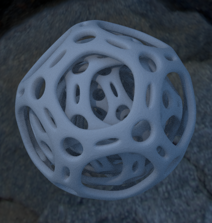
    3d Tutorial | Nested Dodecahedron | 3dsmax

    Here's an example render of the final result:
    nested_dodecahedron_forum.jpg
     
    Last edited: Jul 8, 2015
  20.  
    Last edited: Jul 9, 2015