Supported Wires Shape and Size

Discussion in 'Design and Modeling' started by RRRarch, Feb 5, 2014.

  1. RRRarch
    RRRarch Member
    Hi, so I am trying to make an accurate scale reproduction of some early 20thC steel work, which includes a variety of standard rolled steel shapes. Of course these steel shapes were themselves designed to save material by using thin walls to efficiently create strong shapes, and you can imagine that translating these shapes into a FUD-acceptable thickness at HO scale is not completely possible.

    I will readily admit to not understanding the guidelines when I started converting my model into something that could be printed, and after the hours it took to fatten up all of the members to 0.3mm, I tried to send the thing to print anyway knowing it would probably get flagged, and it did.

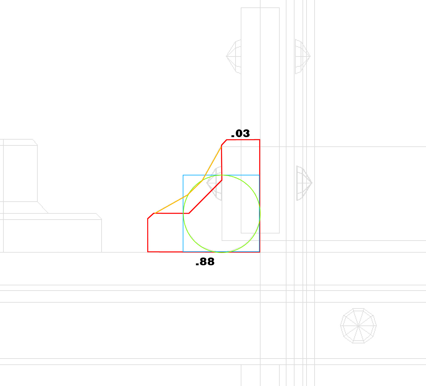
    I still want to keep the steel angles in my model as thin as possible, and angle-shaped, but I don't want to waste my time by redoing them in a way that will get rejected again. Currently the structural angles are supported wires that are "L" shaped in section. The legs of the "L" are 0.88mm long, but only 0.3mm thick. Due to the "L" shape, I know they are stronger than a piece that is 0.88mm x 0.3mm, but I get why they were rejected. The current profile is in red in the attached image. [EDITED TO ADD: The attached image shows the wrong thickness for the flanges of the angle. They are 0.3mm thick]

    I believe the section for supported wires is required to be 0.6mm thick to be acceptable. Must this section be square (blue), or can it be circular (green)? I really prefer to just add the area outlined in orange to get the thinnest measurements up to 0.6mm, but even then I feel the profile of my steel shapes will be pretty badly compromised. Just by looking at the image I have created, I am confident the current shape outlined in red would be stronger than either the blue square or green circle profiles (in bending and in shear). Sigh.

    Any other suggestions? Can anyone tell me what I have to do to get this through? I feel it is pretty much guaranteed that users of this site will always be pushing the limits of what the technology is capable of.

    Thanks

    angle.jpg
     
    Last edited: Feb 5, 2014
  2. mkroeker
    mkroeker Well-Known Member
    Check with service if a protective cage (with sufficient wire thickness) around your delicate model would solve the problem ?
     
  3. RRRarch
    RRRarch Member
    How does one check with customer service? I am reluctant to pursue that solution since the model is already at about $100, and I'd like to avoid having to pay for wasted material. I'm also under the impression that the wire thickness issue is about cleaning more than handling and I don't see how a cage would fix that.

    Thanks.
     
  4. mkroeker
    mkroeker Well-Known Member
    Email service@shapeways.com with the number of the model in question - for instance by replying to the rejection email you received.
    As far as I know, cleaning the detail materials involves heating the model to melt off the majority of the wax, and probably some solvent or soap bath for the rest. If your model is so thin that it must be handled with extreme care once the support material is gone, a cage is the way to go. (Surely it will make the model more expensive, but at least you will have a bridge to sell. Perhaps you can even build at least part of the cage from contemporary girders or similar "useful" extras.)
    If on the other hand your parts are so far beyond the practical minima that they cannot even be printed successfully, pushing the limits of technology does not necessarily mean these limits will budge.
     
  5. RRRarch
    RRRarch Member
    I've communicated with support, and I still do not feel confident that I understand what I need to do to alter my model, since their answers have always been to general. It is going to take hours for me to make any changes to it, and I really do not want to waste time making changes that are not going to be accepted. The diagram I have attached shows cross sections though the typical supported wires that make up my model. The "L" shaped section at the lower left shows what the sections currently look like. While this has details that are only 0.3mm thick, they make up a piece that is 0.88 square. I still know that this is stronger than the circular or square sections shown next to it.

    The top row shows how the "L" shape could be thickened. The first one on the top left has no pieces less than 0.6mm, but it no longer looks like the piece it is intended to represent. The top one on the right shows the "L" shape combined with a 0.6mm square. I don't like this shape either, but can I assume this is okay? The top middle drawing merges the "L" shape with a 0.6mm circle. This is slightly better, but it is still more of a triangle in section than an "L," which is really what I am trying to create.

    So, are any of these alternatives acceptable? Are there any other shapes that could work, and would be closer to my original design?

    Thanks

    wire sections.jpg
     
  6. stonysmith
    stonysmith Well-Known Member Moderator
    Top middle is likely going to be your best choice. But. How long is the piece, and is it attached to a wall? In your original drawing it is shown as being mounted to a wall, with the flange sticking out. That (should not) be considered a wire.. it's a wall. A wire is where the cross-section does not touch anything.

    Remember: there are two possible rejection reasons here. One is because some floating wire is too thin, but they also sometimes reject models because they feel that DETAILS may not be able to be reproduced at the fidelity that you desire. Unfortunately, that second reason is quite subjective, and designers currently have no way to communicate to the production team what level of loss of fidelity would be acceptable.

    The other major thing to keep in mind is physics.. if you have such an L bracket with a (large) weight on the end of it.. then even 0.8mm may not be thick enough to support it.
     
  7. RRRarch
    RRRarch Member
    Thanks for your reply. I was surprised the tech support person who answered me did not seem to understand my drawings or the issues I was trying to get help with. The responses seemed to really just say, "everything must be 0.6mm or thicker," which I get, but it seems like there is still room for interpretation.

    The original drawing shows some of the other pieces beyond (in grey) that the L is attached to, but it is only attached at the ends. The longest of these "wires" spans about 30mm from attachments at both ends, but most of them span less than half of that. All of them are interconnected with other Ls or girders to form braces and trusses.

    I wish they had a smarter system to automatically structurally evaluate our models, since anyone with a background in structural design could tell you that a truss of small parts is much stronger than a single small part on its own.
     
  8. stonysmith
    stonysmith Well-Known Member Moderator
    As such, I happen to fill those shoes...

    Here's an analogy: The movie industry uses "sugar glass" for fight scenes so that it will break on contact. They don't use Bullet Proof Glass.

    FUD is closer to sugar glass than it is to BP glass. It's fragile at thin diameters. Just because some object (truss beams) work well in steel at some thickness, that doesn't mean that the same beam would be sturdy in sugar glass

    You must take into account the strength of the material in addition to the geometry.

    30mm???? gulp! I've had problems with wires breaking at FIVE millimeters!