RHINO USER with stl mesh issues

Discussion in 'Materials' started by MODbot, Jul 11, 2012.

  1. MODbot
    MODbot Member
    I created a simple 3D mesh basket in Rhino. When I run the basic repair in Nettfabb the program closes all the holes on the bottom surface of the basket. (these are holes that are intended to be there) The basket has holes in the meshing on all five sides that are the same spacing and depth. I can not understand why it is closing those holes only on the bottom. Can someone tell me what is wrong with the bottom surface so that I can print the file as a mesh basket and keep the intentional mesh holes on all 5 sides.

    I have uploaded my stl file to this forum. If anyone has any feedback I would greatly appreciate it.

    Thank you,
    Susan
     

    Attached Files:

  2. stonysmith
    stonysmith Well-Known Member Moderator
    [warning: MathSpeak below]

    I know the "reason", but not how to fix it in Rhino. I use Truespace, and this happens to me all the time. I've had the same thing happen to many of my attempts at such a surface with holes in it.

    The problem here is that (too many) points are co-planar. The STL triangularization algorithm is getting lost when trying to generate triangles, and it is reaching beyond what you know as the nearest vertex - to grab one on the far side of the plane.

    I have found that one way to to fix this is to make the surface slightly convex, or at least, non-planar. Attached is a picture of what I'm talking about.

    convex.jpg

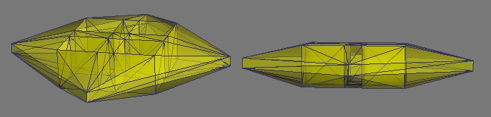
    It doesn't take much of an offset to "fix" the problem .. as small as a .001mm offset is plenty, and won't show up when being printed.

    If you setup the surface so that the points are not all in the same plane, then it won't try to generate the triangles to the far extent of the object.

    Basically, what you're enforcing is that the triangles YOU pick will be kept, instead of allowing the automated algorithm try to decide for you.
     
  3. MODbot
    MODbot Member
    stony -
    Wow. That is really interesting. Thank you so much for your suggestion. I am at work right now but will try it as soon as I can. It might not be til tomorrow eve but I will let you know if it works.

    I am just curious - as a general question. I am a pretty competent 3D modeller having done it for about 6 years now. And yes over the past year I have realized that 3D modeling for 3D printing has a whole new list of parameters that you never have to think about when you do it for rendering. Sometimes though it just seems so arbitrary.

    Is there a way to get a grasp on the big picture? Or, is there a software other than rhino to use that might prepare objects better for print?

    I'd like to get more of a grasp on something. otherwise it seems like its always hit or miss when going to print. I would like to be able to competently prepare the model for printing and know that it will be good to go for printing without having to cross my fingers at the end and then play a guessing game with trouble shooting as I end up doing right now.

    Let me know if you have any advice as I see you have been printing for a long time now.

    Thank you again, Susan

     
    Last edited: Jul 12, 2012
  4. stonysmith
    stonysmith Well-Known Member Moderator
    Welcome to the Future.. It's a whole new world!

    A model that is designed for making a good looking screen render can completely ignore the laws of physics. Unfortunately, when you move into the 'real' world, you need to honor those rules. The other challenge is that several of the available materials are not all that strong at certain points of the process - stuff tends to break, snap, go "ping", etc. and the rules are designed around making the most viable printing process available.

    The 'rules' are by no means arbitrary, albeit that I admit that they may seem that way to an additive manufacturing newbie. I do feel that some of the design rules here at Shapeways still lack a bit of the background information as to "Why is it this way?", but the team has been doing a good job of trying to improve the explanation of the rules. Granted, there is more to do yet, and I know that more updates are forthcoming.

    I happen to have an engineering background. Those many days in physics classes are paying off as I try to design hyper-fragile stuff in FUD. The trouble with it is that I know the background reason for some things, but my explanation may not always be understood by an "artist". But.. don't even ask me to design a statuette. I've got no "organic" modeller bone in me.

    Don't hesitate to ask questions. Challenge the boundaries and contribute (positively) to getting the rules updated with descriptions that make more sense to people from varying backgrounds. My single caveat is "Search the forums first" - there's a good base of knowledge developing here.. your question may have already been discusse.

    Rome wasn't built in a day, but it now has over 10m tourists per year. Maybe someday, so will (our) Shapeways shops.
     
  5. MODbot
    MODbot Member
    Thanks Stony for your feedback again.
    I have a masters degree in architecture. I have a general understanding of physics and yes that things need to be structurally sound to stand in this world. This all makes perfect sense to me and I understand these parameters when I go to print something. Materials break in the real world when they are not strong enough to support something. yes of course.

    The errors that I get are usually nothing like this. In example the question you just responded to regarding making a surface convex so that the computer does not confuse the code. These are the types of parameters that frustrate me.

    I love 3D modeling and the excitement of getting a print back. I am definitely going to keep at it. I just wish there was a more logical way to understand some of the reasons why something can not be printed so that I don't waste time building something that way. Do you know what I mean? Do you have any suggestions for grasping such an understanding?

    Thanks,
     
  6. Realize the three biggest mistake when modelling is not checking if;
    1. Object is manifold
    2. All the faces normals on the surface point away from the center of the object.
    3. There are no vertex doubles.

    Steps 2 and 3 help insure that step 1 is OK.
    Also anytime you add another object, repeat steps 1 to 3.
    1 tiny mistake will make it unprintable
    .
    Two good programs to help check are Netfabb Basic and Meshlab(both free by the way, with Meshlab having way more options for repair, manipulation.)
     
  7. JACANT
    JACANT Well-Known Member
    I'm afraid your file is beyond repair.
    If you go back to your original Rhino file you will see there are two open areas at the bottom of the side panels. I think if you fix this by creating new faces there, it should solve your problems. There maybe other anomalies besides this. It all depends how you created the original file.
    You will have to 'boolean, union' all the meshes together, then check for any naked edges, before you export it to stl. I hope that fixes it for you.
     
  8. MODbot
    MODbot Member
    thanks so much for your feedback Jacant.

    which open areas are you referring to in the side panels?

    I left the surfaces that were touching another surface uncapped so that I could join them to the surface they are next to. Is this what you are referring to?

    if these are not the areas you are referring to as open could you direct me? would it be possible to do a print screen and circle the area in adobe?

    again I really appreciate your feedback.

    thank you
     
  9. JACANT
    JACANT Well-Known Member
    The face at the bottom of the side panels is completly open, you can see inside. As 'stonysmith' explains the software is trying to close the hole but in doing so it does not know where the edges are or should be. This fault was created as you exported it as an stl file, by leaving the face open.
    basket.png
    There are a number of ways to create this model. I personally use Autocad which creates solids.
    Firstly I would draw a 2D drawing of each side and bottom. Then create what are known as regions, In other words I use a boolean command to subtract the inside shapes from each rectangular side and bottom. Then I would extrude the resultant regions to give them the required thickness. I would then place the four sides and bottom together. At this point you want the sides and bottom to overlap each other. From there you can do another boolean command to join the five solids together. Making one solid object which can be exported as an stl file. If you are creating the model with meshes, you can still use a boolean command. The mesh is just a skin with no apparent thickness. The model would have to be watertight. In other words you would not be able to see insde the walls which have zero thickness. This is why the software thinks it is a hole and trys to repair it by creating a face to close it
     
  10. JACANT
    JACANT Well-Known Member
    I think I should explain further. The attached image is one of my models which I have sliced, so you can see inside.
    slice.png
    The top model is 'Hollow' while the bottom model is 'Solid'. This looks confusing because they both look hollow. The machine what prints the file just needs to know where the outside of the object is using face normals. The solid model just has one outside edge . Whereas the hollow model has two outside edges .Confusing again. The way the machine understands this is that there is a hole 'tunnel' between the two faces which have to have a minimum thickness between depending on the material required.
     
  11. MODbot
    MODbot Member
    Jacant
    wow. thank you for posting that screen shot of my model. That was a really careless error on my part.

    I am going to try to rebuild it the way I was originally intending to do it and see if it works. If not, I will again read over what you explained below to try to trouble shoot.

    Thank you Jacant. The screen shot was so helpful.

    Thanks, susan.
     
  12. JACANT
    JACANT Well-Known Member
    I take it the size you want is 11" x 4.5" x 4" . Well I have fixed your file but you will get a shock when you see the price.
    Converted to mm it is 297.4 x 114.35 x 101.65 which works out at 334.26 cubic cm. Expensive. This is why people create thier models to be hollow. Get yourself a copy of Netfabb http://www.netfabb.com/basic.php
     

    Attached Files:

  13. MODbot
    MODbot Member
    Thanks again Jacant. I really appreciate it. I wasn't expecting you to fix it for me also! Wow. Thank you.

    Yes I knew it would be expensive. I am doing this as a favor for someone else. and well thank you for doing the favor for me.

    I do have nettfabb basic. I am not entirely sure how to use effectively - obviously. Can you please tell me what you did in nettfabb to get this model corrected. I would be most appreciative.

    Thank you again Jacant!!
     
  14. JACANT
    JACANT Well-Known Member
    I did not use Netfabb to fix all of it. I have a copy of it but It needed more than what the basic program offered. I used a program called Viscam Mesh. https://www.marcam.de/cms/viscam-mesh.84.en.html
    What I did was delete everthing inside the main shell including the overlapping faces on the base. I then extruded the five remaining outside faces to a thickness. This created five overlapping shells. I then opened it in Netfabb and repaired what was left to do. If you open it in Netfabb you will see it is still five shells, but that is OK, because the software at Shapeways will treat it as one mesh and ignore the overlaps. I think that is the only way to make it useable. It was impossible to repair in any other way.

    Regards Rob
     
  15. JACANT
    JACANT Well-Known Member
    I have 'boolean union' the five shells together.
    I forgot, Although Shapeways treats the model as one. It actually measures each individual shell then adds the totals together. So you are paying for the overlaps twice.
    The attached file is now one shell. It is 17.11 cubic cm smaller, so it will be cheaper. I don't know why I didn't do it the first time.

    Regards Rob
     

    Attached Files:

  16. stonysmith
    stonysmith Well-Known Member Moderator
    This has not been the case for some time now. I just uploaded this model http://shpws.me/aKtk - it is two overlapping 10mm cubes (1.0cm3 each), and has a total volume of 1.75cm3
     
  17. JACANT
    JACANT Well-Known Member
    Hi Stonysmith,

    I beg to differ

    Can you explain the different volumes in the image.

    The first is five shells. Volume - 334.26 cm3

    The second is one shell. Volume - 317.15 cm3

    The third is where the parts overlap. Volume - 17.33 cm3

    Even here there is a diiference 334.26 - 317.15 = 17.11

    volume.png
     
  18. stonysmith
    stonysmith Well-Known Member Moderator
    That's the volume as reported by Netfabb.. what volume do you get when you upload it to Shapeways?
     
  19. JACANT
    JACANT Well-Known Member
    I have not uploaded it. It is not my model.
    I understand what you are saying, Shapeways will not charge you for the overlaps. So 'skosor' could upload the one shell or the five shell model and it will be the same price. Clever.

    Cheers Rob