Single Alloy Stainless Steel 316L (100% Stainless Steel)

Stainless Steel 316L – 3D Printing Material

Binder Jetting

Material info

About Stainless Steel 316L – 3D Printing Material

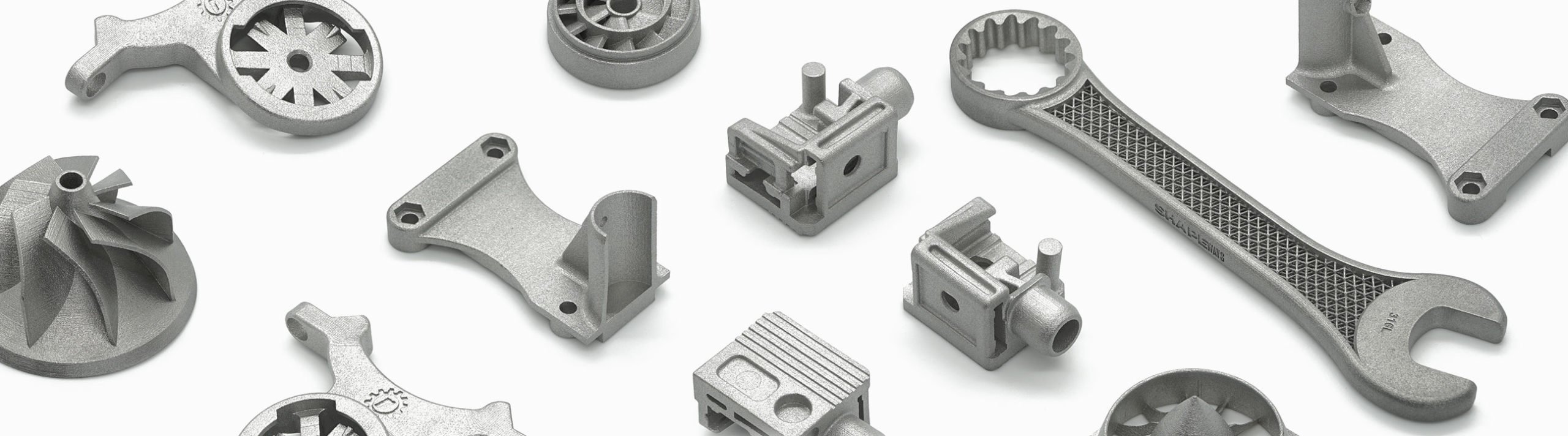
Stainless Steel 316L is popular for use in many industrial applications.  It is known for its excellent corrosion resistance and superior tensile strength at higher temperatures. This material is silver in color, this material features a granular finish that can be polished.  

Stainless Steel 316L is manufactured using Binder Jetting Technology (BJT) from Desktop Metal on a Shop System. Unlike our Steel offering that is infused with bronze, this material is a single alloy, 100% Stainless Steel.


Color & Finishes

Processed
With a semi-matte finish and rough surface, parts are media blasted after sintering

Technology

  • Binder Jetting

Technical Documents

Material Properties

Ultimate Strength (ASTM E8)
505 ± 16 MPa (XY)
Elongation (ASTM E8)
76 ± 12% (XY)
Hardness (ASTM E18)
58 ± 2 HRB

Description

Applications
Manufacturing Heat Exchangers, Fasteners, Mounting Brackets
Material Highlights
Corrosion resistance, Easily machined and polished, Higher tensile strength at higher temperatures

Design Guidelines

Bounding Box

Bounding Box Max
155 × 155 × 76.2 mm

Bounding Box Min
10 × 7.5 × 1.0 mm

The bounding box is a 3D imaginary outline of a box that encloses the smallest area occupied by your model. Your model must be within the minimum and maximum bounding box sizes. If the size of the model is close to the maximum bounding box, then the printing orientation will be restricted.

Walls

Supported Wall Thickness Min
Longest Dimension = Minimum wall thickness
3 to 50 mm = 1.0 mm
50 to 80 mm = 1.5 mm
80 to 155 mm = 2.0 mm
Unsupported Wall Thickness Min
Longest Dimension = Minimum wall thickness
3 to 50 mm = 1.0 mm
50 to 80 mm = 1.5 mm
80 to 155 mm = 2.0 mm
A supported wall is connected at least on two sides of the wall, while an unsupported wall is connected only on one side of the wall. Walls that do not meet the minimum requirements may not survive printing and cleaning processes. Additionally, models may still be rejected based on the wall geometry of the model. Please consider the size of your model and reinforce the walls or add support structures as needed as minimum guidelines will not always be adequate for large models.

Wires

Supported Wires Min
Longest dimension = Minimum wire thickness
3 to 50 mm = 1.0 mm
50 to 80 mm = 1.5 mm
80 to 155 mm = 2.0 mm
Unsupported Wires Min
Longest dimension = Minimum wire thickness
3 to 50 mm = 1.0 mm
50 to 80 mm = 1.5 mm
80 to 155 mm = 2.0 mm
A wire is a circular, rectangular or even triangular feature that is thinner in its unconnected directions than its length. A supported wire is connected at least on two sides of the model, while an unsupported wire is connected on one side of the model. Wires that do not meet the minimum requirements may not survive printing and cleaning processes. Additionally, models may still be rejected based on the wire geometry of the model. Please consider the size of your model and reinforce the wires or add support structures as needed as minimum guidelines will not always be adequate for large models.

Details

Details Min Embossed
1.0 mm high & wide
Details Min Engraved
1.0 mm deep & wide
For text, the ratio between width and depth, should be 1:1 and sans-serif fonts are preferred for line weight consistency.

Escape Holes

Single Escape Hole Diameter (Min)
5.0 mm
Multiple Escape Hole Diameter (Min)
2.54 mm
Escape holes are necessary to empty the support material of a hollow model. Two escape holes at the opposite ends of the model is optimal for the support removal process. Please consider the size of your model and make the escape holes bigger or add more escape holes as needed as minimum guidelines will not always be adequate for large models.
A single escape hole at the end of a cavity will not allow material in the corners near the escape hole to fully escape. So we recommend multiple escape holes at both ends of the cavity.

Clearance

Min
0.3 mm
Clearance is the space between two individual parts in a model. If the space among the individual parts do not meet the minimum clearance, then parts can fuse together or can be difficult to clean. This is important for movable pieces like hinges, gears, etc.

Interlocking & Enclosed Parts

Interlocking
No

Enclosed
No

Parts in File

Max
Up to 250 parts accepted

Accuracy

Accuracy ± 5 %
For example: a product with dimensions of 50 x 50 x 100 mm can be 0.05*100 mm = 5 mm bigger or smaller in any direction.

Related Materials

Sandstone- 3D Printing Material
Application: Figurines, Architecture, Terrain, Scans, Art Sculptures, Avatars
Learn More →
60% Stainless Steel / 40% Bronze Matrix Material
Steel- 3D Printing Material - 3D Printing Material
Application: Tools & Accessories, Dice, Home Decor, Small Sculptures
Learn More →

Stay up to date on promotions, case studies, and more.