Parametric Modelling Interest Group

Discussion in 'Other Interest Groups' started by arturdabrowski, Jul 3, 2015.

  1. I noticed there isn't an interest group for parametric designers, so here it is:


    Let me start off my introducing myself, I am Artur, I come from a background in architecture, so I'm all about designing at all scales. I use rhino (a nurbs software) and grasshopper (a scripting add-on) to create my designs here at Multiply Like Rabbits.

    For those who are unfamiliar, parametric modelling is different than traditional modelling. If you think about traditional 3d modelling, every action to the model is more or less permanent to the model, much like sculpting a piece of clay. Parametric models on the other hand are defined by a string of operations, much like a mathematical function. To create a parametric model, you change the function (x=y.... x+1=y) and change the parameters (x=5.... x =8). This way of working inherently creates multiple iterations of a single design.

    One application is to create a model with multiple ring sizes without uniformly scaling the model. Among other uses, as we'll hope to see below....
     
  2. pete
    pete Shapeways Employee CEO
    Hi Artur,

    welcome! 3D printing suits itself perfectly for parametric design.
    I know there are others very interested in this topic.

    Pete


  3. Hello Artur,
    I didn't know what parametric modeling was until I google searched it, but I think this parabolic hyperbowloid I designed falls into the category.
    Screen Shot 2015-08-09 at 5.54.26 PM.png
    I also designed a tool ring that i now wish I could change the size of without scaling to preserve wrench dimensions. can you explain more in-depth about how you can scale a ring (without scaling it) using parametric modeling? Screenshots would be nice!
     
  4. JACANT
    JACANT Well-Known Member
    Most of my work was done with Designspark Mechanical http://bit.ly/1eFEMfS It's free
    It is a solid modeller, fully parametric but with no hierarchy. It can create components and assembly.
     
  5. ldemrys
    ldemrys Well-Known Member
    I use Solidworks 2005 for ALL my designs. As I understand it, Solidworks IS a parametric modeling program. I've worked with Lightwave, Rino, and various other modeling programs. And, to my mind, Solidworks is ideal for the 3D printing world. It also has the added benefit of being able to export to traditional manufacturing processes. I could, for example, export one of my models to a traditional 3 axis CNC mill. (By the way. I'm a wanna be machinist)
    As things stand right now, I export my Solidworks models to an STL file than can be scaled in Netfabb and uploaded here to Shapeways, and printed.
    So far I've had VERY good results.

     
  6. Max_Sinister
    Max_Sinister Well-Known Member
    Hi, I'm also very interested in this topic. In fact, I wrote a script from scratch to create fractal STL files. Some of them are already in my shop. So far no one asked me for doing them with different parameters, but I'm prepared.
     
  7. Greetings. I've been frustrated forever by the poor and sparse options for encasing custom electronics. There are off-the-shelf products which are never a good fit in dimension or aesthetics. I've rolled my own many times, always using aluminum, and I would do it again except my latest contraption has an internal 802.11 WIFI antenna -- a metal box is not an option.

    But what an age we live in, for a few bucks I can get a one-off custom plastic case fabricated? Cool.

    I tried a few 3D Linux tools and quickly realized a parametric tool like OpenSCAD would let me model my PCB's down to the component level, let me experiment with different mounting options, connectors, wire routes, component placement. What a blast, I've never had the freedom to put elements exactly where I want them and then build from there. I can't imagine doing this with a mousy push & wiggle tool.

    I'm hoping you folks are not only familiar with parametric modelling, but also with the practical fabrication of parts? Because I have a design, but no idea if it can be "printed". Here's a picture:

    case-top.png

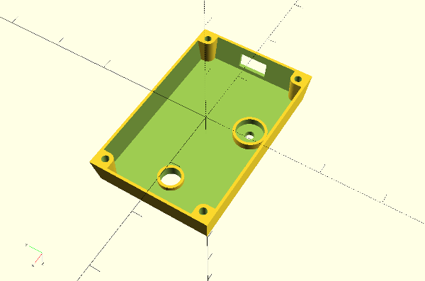
    This is the case top inverted. I assume this would have to be printed inverted as well. Minimum thickness is 3/32. Is this feasible using what Shapeways calls "strong and flexible plastic"? In particular, what about the rectangular opening at the back?

    Any advice is most appreciated.

    Thanks,
    Jeff
     
  8. JACANT
    JACANT Well-Known Member
    Export your model as an STL file. This can checked in Netfabb and repaired if necessary. WYSIWYG.
    Available for Mac, Linux and Windows. https://www.netfabb.com/basic.php

    There does not seem to be anything wrong with your model. Be sure to check the design guidelines for the material you want to use. https://www.shapeways.com/materials/strong-and-flexible-plas tic

    DesignSpark Mechanical and DesignSpark PCB could have been your answer for 'encasing custom electronics'. Windows only I'm afraid. Although if you look on the Forum there may be an answer to use it on Linux.

    Watch the video 'HOW CAN DESIGNSPARK MECHANICAL HELP ME?' on this page
    https://www.rs-online.com/designspark/electronics/eng/page/me chanical
     
  9. Thank you JACANT. I have netfabb running. It fixed my OpenSCAD STL no problems (all simple holes.) Good tool, I will study it further.

    It's exciting to think I can have an affordable custom case made for my project.

    On to the bottom plate....

    Jeff
     
  10. Max_Sinister
    Max_Sinister Well-Known Member
    OpenSCAD is quite a useful tool if you know how to program well. I only discovered it after I had spent some time to add a monogram to the STL files of a case. In OpenSCAD, there's a function to do so.
     
  11. I've been programming forever, so the numerical module approach used by OpenSCAD is natural for me. As a system OpenSCAD seems to lack an overall architecture to help organize large projects. (Or I haven't found it yet.) By assuming a consistent zero point for components, and by using a consistent (but cumbersome) naming scheme for component parameters, I can model spatial relations easily. The code ain't pretty though. It has a late 60's look to it.

     
  12. I just bumped into this group, I am interested in a cad system which is truly totally parametric. We have used (in the serious past) a language called IBM 370 APT/AC. This is Fortran parametric and has anyone seen or used a cad system which can do this? By the way, we built the Space Shuttle with this language and pencils before CAD. using N/C
     
  13. Max_Sinister
    Max_Sinister Well-Known Member
    Are there manuals for IBM 370 APT/AC online, somewhere?
     
  14. FreeCad is a Breps parametric solid modeller software. I tried different software, including OpenScad, Solidworks, Autodesk, Rhino, OnShape, Grabcad, etc, before settling with FreeCad. It's not set up for handling very large projects and it's not oriented towards drawing office use and the needs of design bureaucracies, STP0022.jpg but it's well-suited for one person, or just a few people's use. In fact, once you get used to the drawing tree system, the process of splitting off files and later recombining them is very straightforward. Attached is a drawing done in FreeCad comprising about 112 separate parts. Many are printed separately, some as sprued arrays. Some parts are glued together, many are push-fitted using tabs and slots. I've stayed with FreeCad because I found that when I put things onto the cloud-based systems they were not able to handle the very large file sizes and my assemblies crashed their systems. That's when I started to figure out ways by which I could manage large assemblies in FreeCad.

    Cheers

    BTW image is of an Orenstein & Koppel carriage for use on a garden railway, 45 mm gauge (G).
     
    pendarestan likes this.
  15. ik_ilmar
    ik_ilmar Member
    Hi Guys,
    I found very interesting topic here.. I think, each software has many advantages and .. disadvantages. Parametric modeling is good when you want to design something quickly, precise, perfectly matched and.. with multiple versions. But several years ago I discovered Rhino, then T-Splines, Then Grasshopper. Almost all models uploaded to my store are designed in Rhino, some of them Blender 3D or Autodesk 360. I never thought, that free-form designing process can be so easy and fun with rhino. Also I tried Autodesk Fusion 360 - I think it is the same like SW, but with T-Spline (Sculpt) module, and free of charge.
    If here are any Grasshopper experts I would be appreciated if you could share your knowledge.. and continue the topic