Hi there,
I'm working on one of my biggest project, even still I begin 3d modeling 1 month ago, It's a Sturmgeschütz IV
I Have made appoximately between 40 and 50% of the work : I 've modelled The crew hull, the motor hull, part of the fonctionnal 75mm canon (functional in elevation and traverse). Im still working on the commander and the MG gunner turret. I plan to do functional hatch, wheel, and tracks.
So I need some help upon this detail and some opinion obout the work I've done (I'm working on blender 2.78)
All part seen

Motor hull

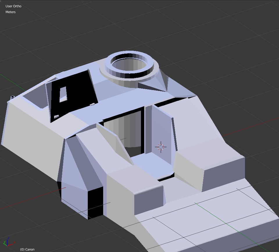
Crew hull

Crew hull with Commander turret
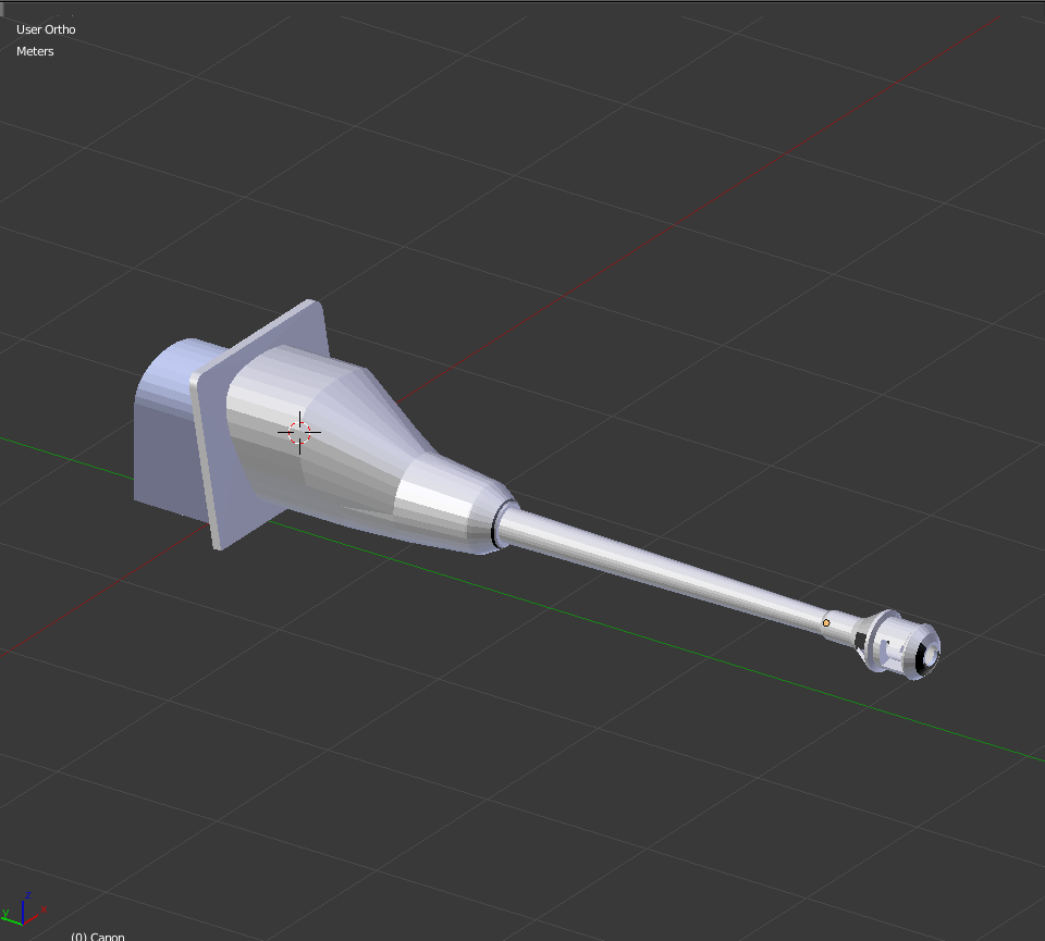
Canon
I would like to have some advice upon which material could fit to this project and modelling proccess
I also plan to separate part as seen on this model notice

Thnaks in advance
")