Here is my first attempt at some 3D printing - some wing tips for a radio controlled model aircraft.
Main wing left and right tips:
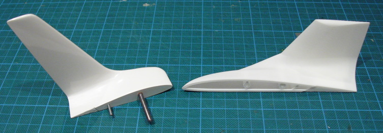
Canard left and right tips with template:
 Background
The shape of the tips of the wings of an aircraft is actually a very important factor in how the wing works. With full sized aircraft there is no debate that the wing tip shape is important - just look at the time an effort that full sized aircraft companies put into the design of the wing tips. With radio controlled models there is some debate as to whether they have any real effect (for lots of reasons that we won't go into here) on the model. However there are (at least) two important points about the wing tips: they need to be the same shape on both sides, for appearance reasons alone it is sometimes important to have a particular shape tip.
There are various methods of constructing the wings of a model aircraft, however, in all construction methods there is the issue of the wing tips. If you purchase an expensive fibreglass molded model it will come with molded wingtips constructed by the manufacturer. However, if you are building a one off model for yourself then the only really viable alternative for most people is to carve and shape the tip from foam or balsa wood and then use it as-is or cover with fibreglass. The carving and shaping make it difficult to get exact shapes, let alone both tips exactly the same. Similarly the reproduction of precise airfoils at the small sizes typically encountered on wing tips is almost impossible.
So 3D printing struck me as perhaps the ideal middle road - a not too expensive custom shaped wingtip.
So my test was to attempt a 3D print of the wingtips for a 2.56m wingspan aircraft that I am currently building. I took the existing 3D CAD models of the design and exported some wingtips for the model. Unfortunately at this stage I can't show the total effect because the aircraft is still under construction - and I stopped building the wings until I had these wing tips so that I could check the construction and attachment mechanism, so I can't even show the wingtip on a finished wing at this stage.
Here is what a molded fibreglass wing tip looks like, and the part that I have just had printed.
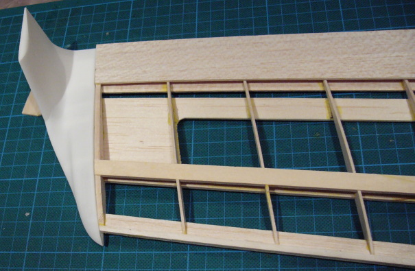
This is the general idea of the tip on the end of a balsa wing.
 What was I looking for?
The key issues (from my perspective) are:
- acceptable strength
- minimum weight (at acceptable structural strength)
- appropriate finish and surface
To meet these objectives I designed as follows:
- White, Strong Flexible as the material.
- 1mm wall thickness throughout
- appropriate internal spars to take small flight loads
- 2mm holes to permit internal filler to be blown out
- appropriate mounting points for attaching to the wing
The result was two 3D print parts:
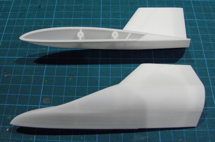
- A pair of tips (left & right) for the main wing of the aircraft, joined by two short joiners. These are quite large - being designed to fit on the end of a wing that has a 150mm chord (distance front to back of the wing) - volume approx 29.5 cm3 for the pair.
- A pair of tips (left & right) plus a template for drilling holes in the wing tips for the canard on the model. These are much smaller as the tip chord is only 70mm - volume approx 5.41 cm3 for the pair.
What arrived
So today my box arrived and I had the excitement of a look inside. What was inside was as follows:
a) A bag with the smaller tip assembly (for the canard) as I designed;
b) A larger piece of bubble wrap with the two larger tips wrapped inside. The two short joiner pieces between these two tips had 'disappeared' - and it looks like production had separated the parts for me. Luckily the short joiner pieces were not actually important, however, had they served a purpose I would be missing them.
My initial impressions are that the material and finish is exactly what I was after. The shape was exactly what I was expecting. They felt slightly heavier than I was expecting - not that I had an exact expectation because I couldn't find an expected density for WSF anywhere.
What about the weight?
Left tip: 15.4 gm (density assuming designed volume: 1.04gm/cm3)
Right tip: 17.2 gm (density: 1.17 gm/cm3)
Small assembly: 6.1 gm (density: 1.12 gm/cm3)
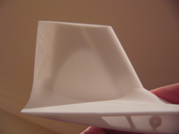
Closer inspection (holding the parts up to the light) shows that even though I tried to design in 'blow out holes' to permit the air to clear the filler from inside the parts this has not worked that well. All the parts show significant filler inside, with the heaviest tip significantly affected.
Looking through one of the tips you can see the dark area where the filler has been left in. The other tip has significantly more filler.
Overall I estimate that the parts are at least twice as heavy as a balsa foam sanded shape that is covered with fibreglass - however I don't think that the weight is a problem at this stage.
Surface finish
I have to admit that I had an ulterior motive in connecting the two larger wing tips into one 3D print: I wanted to get them printed at the same time with the same orietation. I thought that this would maximise the chance of the two wing tips having the same steping marks due to the resolution of the print. Looking at the result in detail this doesn't appear to have been effective - or perhaps there is a variation in the post-production blasting of the parts. In either case the parts show quite different finishing smoothness.
Proposed finishing
My proposal to finish the parts is to spray with a sandable primer and then spray finish with auto paint in an appropriate colour. My objective is to use the primer and sand to get a slightly smoother finish - then paint with the final colour. I will see how this goes and report back in due course.
Summary
Overall I am quite impressed by this first attempt and I am sure that the parts will be usable. The first step is to attempt to remove the filler...
Issues and Questions
There are obviously a few issues that I need to resolve:
a) What happened to the parts that were supposed to connect the large left and right wing tips? Was there something wrong with my 3D design, or did something happen during manufacture? Looking at the design there is obviously an issue with using air to blast out the filler from the tip and perhaps it was during this phase, or perhaps the 'smoothing' phase that the parts became separated.
b) Why isn't the filler removed from the parts? Due to the size and nature of the part my design has 2mm holes in the furthest area to permit air through to expel the material - this doesn't appear to have worked completely in this case.
c) I did not consider how the filler would come out of the mounting holes - these are 2.4mm holes. The holes appear slightly undersized and currently have a lot of filler in them.
If anyone has any helpful comments that would be great - or perhaps I should raise some of these issues in the "3D Printing" forum?
Thanks,
Tim