Yay, it's here! My first Shapeways model, not very original I guess, just the first thing I wanted to try, it has lots of air inside, so it's not too expensive for a model this size
")
 (EDIT: the current model has been enlarged: sides 18 cm, 14.5 cm high)
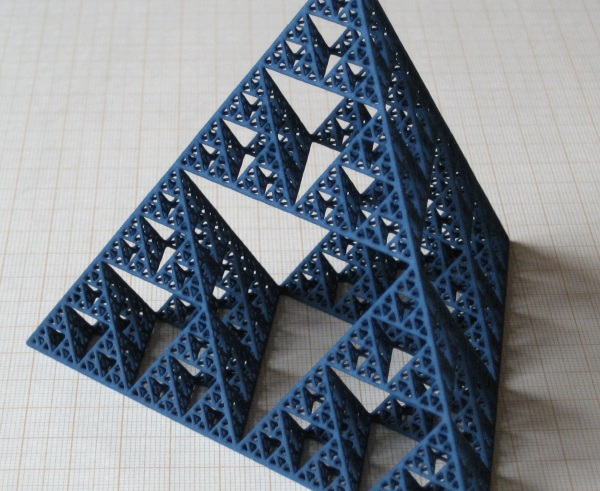
The sides are about 12 cm, it's 9.5 cm high. The model has 499.994 faces, there are 4096 struts. It feels pretty sturdy, no flexibility at all of course.
(EDIT: this problem has been resolved by making the model bigger)
Though I'm pleased with the result, there are a few issues due to the thinness of the struts: struts that are in the plane of the printing layers are noticeably thicker, some of the thinnest struts (<10) didn't make it through printing and cleaning, see below:

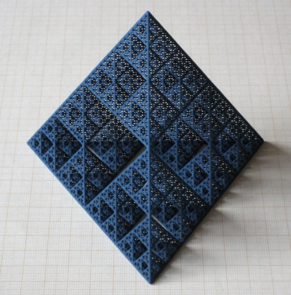
Another view:
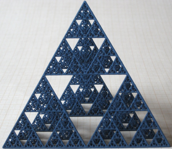
and another:
Finally, I'd like to thank the good people behind POVRay and MeshLab for enabling me to make the model, and of course everybody at Shapeways, without whom this wouldn't have been possible
Oh, and I almost forgot Sierpinski himself...