Looking into this some more it appears as though the axis references for the model page view and the axis references for the render views are not necessarily consistent within Shapeways.
So the first thing I did was to draw XYZ axes in Tinkercad using their standard. Over there the horizontal workplane is the XY plane, with +X to the right and +Y away from the keyboard. The +Z axis is upwards towards the ceiling. So when we upload that and look at it in the model page render after the preliminary auto movements finish we get the same orientation so here Tinkercad and Shapeways seem to agree:
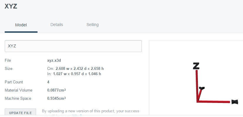
However when you look at the x,y,z render options things begin to get weird:
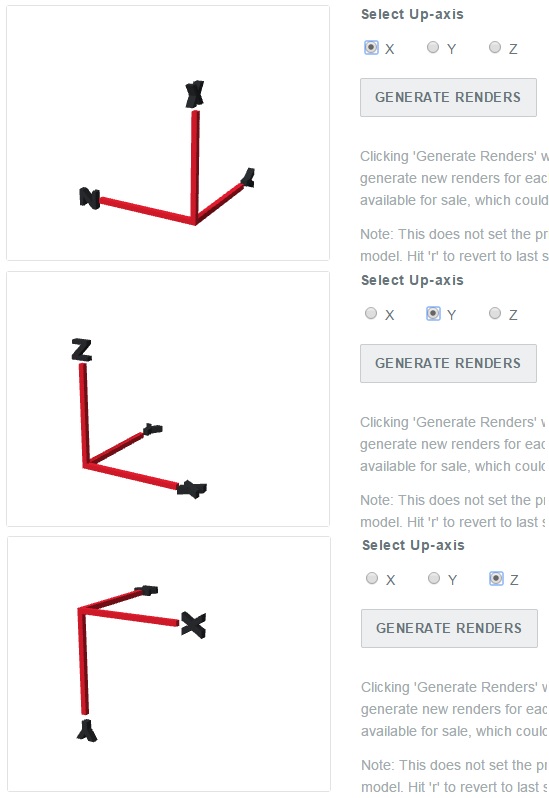
I realize this is all a bit arbitrary but in another sense there must be a clear standard for file formats that define "true" x,y, and z directions. In order to get Tinkercad to match Shapeways +X remains the same pointing to the right, +Y points upwards, and the Z axis is on the horizontal workplane with +Z pointing towards the keyboard. So someone is doing something differently which isn't necessarily surprising, but it seems to me that since the model preview in Shapeways does not match the render options that it's the renders where some axes are swapped and at least one sign error has crept into the works. Again I wouldn't really care other than the fact that the Shapeways render axes appear to have changed at some point in time either for the better or for the worse.
------------------------------------------------------------ -------------------------
One more possibility that I can't check now (Tinkercad is being updated) is that the old pendant file was uploaded in stl format and the new ones and the XYZ example were uploaded in x3d format. Perhaps Tinkercad and Shapeways are using different axis references in those two file formats. I love troubleshooting!