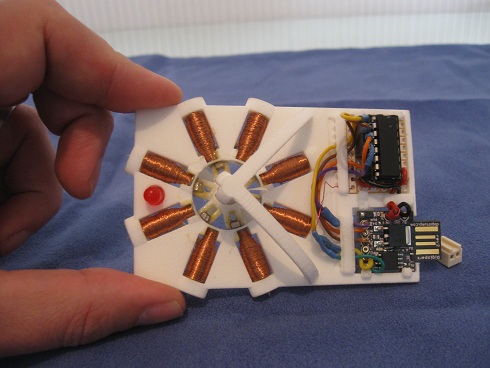
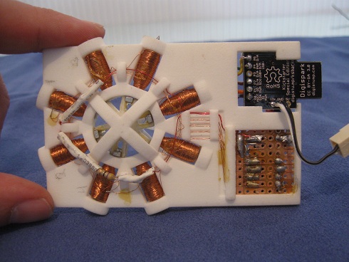
This is a programmable stepper motor and driver that I made out of some nails, magnet wire, neodymium magnets, a digispark microcontroller, and a 3D printed piece that I designed around these things.
Here's a link to the video on Youtube
http://www.youtube.com/watch?v=paT63-8DLbs&feature=share &list=UUVG1PI-SceL_F6BVS2grLbQ
(Can I post a video directly? )
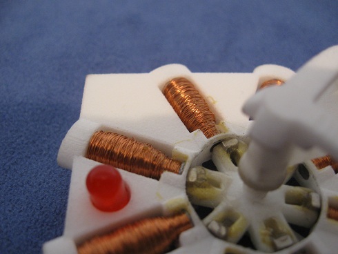
My goal was to make something about the size of a business card that moved. You can't exactly fit it in your wallet but it does indeed move. It just a first draft- there's lots of room for improvement. It has a step angle of 15 degrees (although the way I'm driving it, it is 7.5 degrees.) I saw a schematic diagram explaining how a stepper works with eight electromagnets and six permanent magnets in the center and I thought that layout might look cool. It also does illustrate well how stepper motors work. The white parts were designed in a CAD program, made from WSF material. Rotating shafts are always tricky since too tight a fit and they fuse or have lots of friction, too loose and there is wobble. I got around this by making the ends of the shaft are cone shaped and pointy. They are held in place by slightly wider conical indents. The shaft was slightly longer than the space and I got it in there by pulling it open a little bit. It was then held in place by the springiness too. The material needed to be flexible for this. It's not an ideal solution for every situation like this (it can't support much weight pulling perpendicularly to the shaft) but it worked ok here. The magnets are held in place by epoxy. (It's not fun working with strong little tiny magnets that want to stick together but are also covered with epoxy. It was a mess and there was swearing. It was also important that they all be oriented with the same polarity facing out.)
For those who are interested, the driver chip is a uln2003 transistor array and it is being controlled by a digispark which is a little arduino compatable microcontroller. It can be programmed by plugging it in the usb, but it needs an external 20V source to run it. (I know 20V is high but I just kind of guessed with the electromagnets and that's what they needed to run. Originally, I had it work with12V with the electromagnets repelling the rotor instead of attracting it, but I think that began to demagnetize the rotor magnets and it gradually stopped working.) In this video, I just have it run through a series of movements to show that it really works. I find it's best to shoot your project videos soon before you fry something and it doesn't work anymore. Not that that is going to happen here...