slip fit

Discussion in 'Design and Modeling' started by 21636_deleted, May 21, 2009.

  1. 21636_deleted
    21636_deleted Member
    Hi All,
    Im new to shapeway so im trying to read lots before i ask silly questions but i cant find an example of this.

    What im after is a tube and an end cap that fit tightly together but can be pulled apart with a bit of force. I want to end up with something that is reasonably splash proof.
    Im pretty sure the easiest way to do this is have the end cap slide into the tube but my query is how to get them to fit tightly but not too tightly.
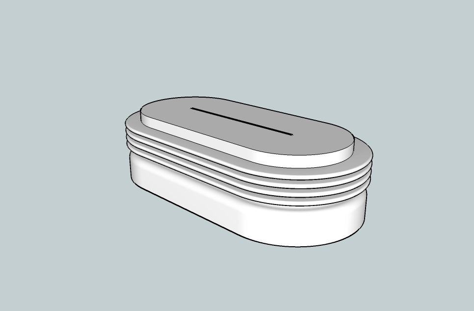
    What ive come up with is the cap having fins around the outside that are just big enough that they will have to bend to enter the tube (see pictures).
    An alternate is make the cap just much simpler but put a grove in it and fit an o-ring
    Anyone got any other ideas?

    From what ive read so far
    -i will print them seperatly so they dont fuse
    - for a part to slide into another part a gap of 0.1 - 0.2 mm is required (obviously my fin design will bend that rule).

    Anyone got any thoughts on dimensions for my fins to get a reasonable flex but not breaking from being used regularly. (eg width, depth and amount of overlap with the tube)
    Thanks for any thoughts.


    the cap
    insert.jpg

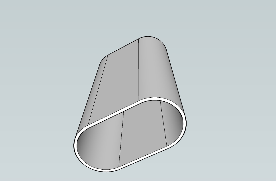
    the tube (about 21mm x 40mm)
    tube.jpg
     
  2. 21636_deleted
    21636_deleted Member
    here is another design i thought of for the cap
    might have more flex then the fins in the previous example
    obviously these are a little rough and missing some details eg. there will be a tab on the top to enable the cap to be pulled from the tube.

    forgot to mention previously that im aiming for the WSF material

    any thoughts, comments?

    Untitled.jpg
     
    Last edited: May 21, 2009
  3. lorddarthvik
    lorddarthvik Member
    I´m not sure, but by checking my WSF prints, I think neither of the two designs would work as intended, as WSF is not That flexible. If the parts that should bend are thin enough (1-0,5mm?) it may work, but there is no guarantee. I´m about to design a case just like yours, for a gift mini soap box, but I still couldn´t come up with a good design for the cap.

    I´ve checked the forums too, and I haven´t found anything exactly like this done before, so it would be great to come up with a solution for this. Personally I would go with the first design, because it has more room for size errors and has a better chance to bend into place, especially when inserting the cap. I remember reading about something printed that had to had precise fitting, and if I remember correctly it had a clearenc of 0,4mm. The problem with this is, that 0,4 may be too much or too little for your design, depending on the printing orientation, which you cannot set.

    I hope someone with some experiance in this matter drops by and gives us a better answer :)
     
  4. 21636_deleted
    21636_deleted Member
    thanks for your comments,
    I acctually thought the second design would have had a better chance to bend into place.
    just to clarify ive included a cross section of the second design.

    the bottom in this image slides into the tube first. The bottom is slightly narrower then the tube and the thin bits will be slightly wider (not sure how much).

    Im currently working on the flexible bits being about 0.5mm

    There must be some simple designs for this but its just made a bit more complex by not know the properties of the plastic ( i will have to do some test prints ) and the printing being imprecise at this scale (there is no pleasing some people :p )

    I will probably end up printing a range of designs to see what works.

    anyone else got any ideas.............

    Untitled.jpg
     
    Last edited: May 21, 2009
  5. 11460_deleted
    11460_deleted Member
    Hi artttt,

    Here is a mechanism that I've had some success with. This picture shows a cross section of a cap/tube.

    As you can see, it uses a 0.3 mm clearance and 0.5 mm radius half circle for a total gap of 0.8 mm.

    The cap wall is 1.2 mm thick, and has 3.5 mm long slits to create the snap fingers. If the cap wall is thicker, the slits may need to be longer.

    For a snug fit, you could try a 0.24 mm clearance. I don't think I'd go below 0.2 mm.

    I'd be happy to answer any questions you may have about this approach. :)

    ~David

    snapfingers.jpg
     
  6. lorddarthvik
    lorddarthvik Member
    @ artttt: I thought that the second cap design would be the other way around, sorry :) This way it could realy work better!

    @ jdavidbush: Thats a pretty good looking design, I think I may use that for my soap box cap if you don´t mind! My only question is: how watertight is this solution if the upper half-circle goes all the way around? Can it seal enough to hold inside small drops of water?
     
  7. 21636_deleted
    21636_deleted Member
    Thanks for the alternate design David. I started out with something similar but didnt use slits so didnt think it would work.

    Have you had it printed?
    Your tabs have to deflect 0.2mm does this give a noticable feeling of the cap clicking into place?
    Does it offer much resistance when you pull the cap back out?
    how many tabs have you used around your cap?

    Answers to these questions will help me develop my designs.
    Thanks


  8. 11460_deleted
    11460_deleted Member
    @lorddarthvik: Thanks. :) Feel free to use it for any design you'd like. Regarding watertightness; I wouldn't count on the porosity and tolerances of WS&F to make anything watertight (unless, perhaps, you made it slightly oversized and pressed the two pieces together.) However, it does help prevent splashed water from getting in. You could probably make something watertight with Transparent detail because the tolerances are much tighter and the material is a bit "sticky".

    @artttt: This is the design I used to attach the gears for Gear Ball. The mechanism works great. The pieces require some force to snap together (and take apart), but my tabs are curved and require more force to bend. They definitely "snap" or "click" in place.

    Here is a photo. You can see that I've got five tabs. The "hole" has an 8 mm diameter.
    gear_connector.jpg

    I was thinking, it may work to just put a few tabs around the inside of your cap like this.
    I'm sorry I don't have the other half-circles in this drawing. SketchUp's Follow Me tool was making me tear my hair out. :p
    cap_and_tube.jpg
    ~David