business card holder

Discussion in 'My Work In Progress' started by 151912_deleted, Aug 9, 2012.

  1. Hi ya'll,

    First time on the forum. I'm trying to determine if I should try printing this business card holder as a single unit, or if I should divide it up into 3 parts. Or if this will even work at all.

    The main issue is that i've got a "drawer" that slides out. the space between the "drawer" and the walls are about .27mm.

    I ran the model through Meshlab and then through Netfabb. Ran a fix in Netfabb and the result was "0" shells. Does that make sense?

    I was hoping someone might be able to take a gander at this and see if it could work out.
    I'm not concerned about theft since this is my first time, so I'm just uploading the stl file...
    hope I can get some feedback.
    Thanks,
    Bill
     

    Attached Files:

  2. stonysmith
    stonysmith Well-Known Member Moderator
    Of course, it depends upon the material you chose. I've had success in making FUD models with a gap of 0.15mm, but failed with models in WSF with 0.5mm

    The other issue here is that your model currently is 42 cm3 of material. That's going to cost you $60+ in WSF and $151 in FUD.. a bit pricey for a business card holder (in my opinion).
     
  3. Thanks for the reply stonysmith. I was planning on using the WSF. I thought that I would be safe with a gap of .27mm, but from your reply, seems that might not work.

    Based on this, I'm thinking of scrapping this design, removing the "shelf" entirely, and going for something more simple.


    Bill
     
  4. Hey stony,

    just re-uploaded another, simpler, version.
    I know its a bit expensive, but I want to see how it may work the first time.

    any thoughts on this, using simple white polished?

    wharg
     

    Attached Files:

  5. stonysmith
    stonysmith Well-Known Member Moderator
    Looking good.

    You have a problem with the (shortest side) last hole on the right and left.. nearest the opening.. there is a geometry problem there causing a zero-thickness wall.

    You also have some othe small issues with the geometry. I would suggest download a copy of NetFabb and look at your model using that free software.. it'll identify the issues I'm discussing.
     
  6. Hey stonysmith,

    I did run the model through Netfabb when I first uploaded it.

    So I re-read the shapeways tutorials and did the following

    Re-opened my model in Sketchup
    Exploded all the parts
    Exported 3d Collada file
    Opened Collada file in Meshlab.
    Saved model as .stl
    Opened .stl in Netfabb
    re-scaled the model to its current size
    Ran the repair sequence (default repair, apply repair, etc)
    Re-saved model.

    I'm not sure where you see the 0 wall thickness... What am I missing?
    When I open the file in NetFabb, I do see a few yellow lines that almost make it look like there is a "phantom" wall on two sides of the model. After I run the "repair" sequence, it seems to disappear.
    I'll upload a picture from the NetFABB first step showing the (phantom)...

    B
     

    Attached Files:

  7. ... and the phantom wall..
     

    Attached Files:

  8. stonysmith
    stonysmith Well-Known Member Moderator
    Try this. I loaded it into Truespace and fixed the remaining holes.
     

    Attached Files:

  9. stonysmith
    stonysmith Well-Known Member Moderator
    Let me try to explain what I did. There are some places in your model where the geometry is not "correct", and Sketchup and Netfabb are working against you. The programs ae making an assumption about what they think is correct, but they're not doing what YOU wish. I've studied (suffered with) this condition for years - the programs just can't make the right choices sometimes. For some reason, large flat surfaces that have a number of holes in them tend to develop this condition much more often than slightly rounded surfaces.

    j2.jpg

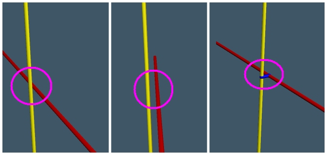
    In the example above, there are two vertexes (lines) red and yellow. In the left hand image, they appear that they would are crossing (connected), but you can see in the center rotated image that the two lines actually do not touch. It does not matter how infinitesimally small the gap is.. they still don't share a common vertex.

    In Truespace, I zoom in as far as I can go, and I try to find the spots where the two lines are not connected the way I expect. If a face is found covering what you expect to be a hole, then somewhere around the edge of that face you will find this problem. Unfortunately, sometimes finding the trouble spot can take a good deal of time, plus good old trial and error.

    Once I've found the spot, I use the "add vertex" tool, and connect the two lines as shown by the blue line in the right hand image. This informs Truespace that I expect the two lines to be connected, and then it will compute the adjoining surfaces correctly. I'll be honest, I'm not sure if nor how you'd do this in Sketchup. One good way to express it... when you're combinging shapes in Sketchup, don't make them meet face-to-face or edge-to-edge.. put just a bit of overlap between between the objects. If the amount of overlap is smaller than the "Minimum Detail" parameter for the material you're using at Shapeways, then you likely won't see the "bump" on the final print.

    Don't let me mislead you.. doing this is not pleasant when there are a bunch of such spots. But, perserverence CAN win out.
     
  10. I'll take a gander at it right now. Much obliged.
    I take it that I should download a version of TrueSpace and start using it in place of NetFABB.
    ...

    many many thanks.
     
  11. Wow.

    I can't even figure out how to import a collada or STL file into TrueSpace.

    Many thanks for your help. I can tell I'm going to need a lot of practice on this.

    I'm still unsure how you identified the problem faces in NetFABB to begin with however.

    Are these the yellow lines that I mentioned as the "phantom wall" jpgs?

    thanks a lot for you help.
    B
     
  12. stonysmith
    stonysmith Well-Known Member Moderator
    I wasn't necessarily advocating that you pickup Truespace.. I was just trying to say that is the tool that I used.
    You will need to keep Netfabb handy.

    The other small issue is that you need Truespace 7.6.0 (still available) instead of 7.6.1 In the later version, they removed the STL import/export feature.

    Yes, the Yellow dotted lines in Netfabb show you where you have holes. When you click "Close Holes", it will attempt to close those holes. If you then observe that it creates walls where you didn't desire them, then you'l need to go back and re-work your original design to try to correct them.
     
  13. Ok, understood.

    Do you think I can attempt to print now? Obviously, I understand that these things can come back screwed up, but in your estimation does it seem likely that I could print this successfully?

    B