N to HOn30 2-8-0 Steam loco conversion project

Discussion in 'Tips and How-tos' started by pinddle, Jul 28, 2012.

  1. pinddle
    pinddle Member
    I'm developing a set of parts to convert a Bachmann N gauge 2-8-0 steam loco into a narrow gauge version for HOn30.The idea is (or at least was) to make the conversion fairly simple, and to leave the choice to the builder as to how much work is involved.Most parts will all be available separately to give a choice for the builder.
    The parts being developed are:
    Tender body - done
    Cab - done ( 2 versions, the mk.1 is in the photos )
    Pilot - done
    Air-pump - done
    Chimney - done
    Domes - done ( new hollow version - done )
    Headlight - done
    Bell - done
    Turbo Generator - done

    Some of these parts are available from other sources, I'm developing them because they are not easy to buy where I live.

    This kit was originally developed for the DC version. I have now adapted some of the parts to fit the DCC version. Scroll down to the bottom for instructions specific for the DCC version.

    Now for some pictures.First, a before and after comparison.Then some of a nearly finished model.
    conv.1.jpg
    conv.2.jpg
    conv.3.jpg

    Next,I'll be showing how I did the conversion with the parts available so far.
     
    Last edited: Dec 10, 2013
    851487_deleted likes this.
  2. pinddle
    pinddle Member
    The parts used for the conversion:
    conv.4.jpg
    Some are still being developed (see first post).
    I'll start with the locomotive.
    Part 1.
    Remove the body from the chassis, you need to remove the handrails from the rear of the cab and unclip the front steps from the smokebox.Pull the body up from the cab end and then push forward.The cab pulls off from the body.To remove the pilot,loosen the front screw on the keeper plate.This allows you to remove the pony truck,giving you access to the screw holding the pilot in place.The new pilot is a direct replacement for this.
    You should have a pile of bits like this:
    conv.5.jpg
    On the body,remove the chimney and domes (the rear one is held on by a screw).Remove the airpump and the foot board that went over it.
    conv.6.jpg
    To allow the new cab to fit,a small part of the front of the footplate has to be removed.See below.
    conv.7.jpg
    The pipes under the right side of the cab are cut back,as the new cab will be in the way.See above.
    conv.8.jpg
     
    Last edited: Jul 28, 2012
  3. pinddle
    pinddle Member
    Part 2.
    Test fit the parts.The new cab fits the same way as the original.
    conv.9.jpg
    Now things can a bit complicated.If you refit the body onto the chassis, you'll find something sticking out where one of the new domes is to go.
    conv.10.jpg
    [A new hollow dome is now available in a new detail set. The mod shown below is not needed if you are using the new detail set.]

    This problem can be solved with a bit of bodging.Remove the body and the weight at the front of the chassis.Unless you plan the use it somehow,remove the lightboard from the front of the chassis,cutting the wires close to the joints.
    conv.11.jpg
    The tabs projecting up can be broken off at the hole in them.This still leaves enough exposed metal for the wires to make contact.
    conv.12.jpg
    Place the wires over the remains of the tabs and wedge something non-conducting in between them to hold them in place.I used a small piece of wood.
    conv.13.jpg
     
    Last edited: Sep 21, 2013
  4. pinddle
    pinddle Member
    Part.3
    The completed chassis:
    conv.14.jpg
    Refit the body and test fit the domes.
    conv.15.jpg
    If you are happy with the fit of parts, it's on to the airbrake.
    I used a piece of 0.5mm dia. brass rod to mount the airbrake onto the small block that the original one was mounted on.I drilled a small hole into the back side of the pump and glued the rod into it.
    conv.16.jpg
    New footboards were made from 5mm wide strips of thin plastic card and glued onto the existing footboards.Some of the boiler side plumbing will need adjusting to make room for these.The arrow points to where the airpump will be mounted.
    conv.17.jpg
    The domes and chimney can now be glued in place, filling any gaps around their bases.Now is the time to paint the separate parts before final assembly and glueing the airbrake in place.The parts here are unpainted so you can see them!
    conv.18.jpg
     
  5. pinddle
    pinddle Member
    The tender.
    There are two options here:
    1.The simpler option is use one of my tenders complete with trucks.Just add some weight and make a drawbar to connect it to the loco.
    2.The more complicated one, which I shall detail here, is to use the donor tender chassis plus a new body.This has the advantage of retaining the all wheel pick-up of the original chassis.

    Part.1
    Some pics of the tenders alongside.
    tc.1.jpg
    tc.2.jpg

    Remove the trucks and N gauge coupler.Remove the insert in the top of the body by pushing a screwdriver up through the rear truck pivot hole.Remove the weight.
    tc.3.jpg
    Remove the footsteps from around the bottom of the chassis.
     
  6. pinddle
    pinddle Member
    Part.2
    Cut off the front of the body, using the first vertical row of rivets as a guide.The cut doesn't have to be neat,see next stage.
    tc.4.jpg
    Cut off remaining three sides of the body, above the chassis.Take care not to damage the conductor strips inside.
    tc.5.jpg
    Remove the small pillars at the corners.
    tc.6.jpg
    Cut down the truck mounts so that they are flush with the small bits of plastic either side of them.Make a cut out at the rear for the Micro-Trains coupler.
    tc.7.jpg
    Test fit into the body, make adjustments if needed.
     
  7. pinddle
    pinddle Member
    Part 3.
    Remove the rear pillar from inside the upper insert.About 5mm will do. tc.8.jpg
    Glue this onto the rear truck mount, top side of chassis.Use the mounting screw to hold it in place (centered).(I used plastic weld for this).
    tc.9.jpg
    Glue some 1mm plastic card to top of chassis, between the conductive strips, to support the weight.I used part of the upper insert for this.
    tc.10.jpg
    Glue the weight to this support.Refit the trucks and drawbar.
    tc.11.jpg
    Mount a Micro-Trains 1015 coupler to the rear of the new body and place onto chassis.Make a lid for the rear toolbox from some thin plastic card.
    tc.12.jpg

    That's it for now.Any Questions?
     
  8. pinddle
    pinddle Member
    A word about finishing.I left any detail off the cab roof because the finish of a curved surface can vary with the printing process.A roof hatch can be made out of some plastic card if you want.
    To get a smooth finish on the roof, the method I use is to paint (acrylic), and sand when dry.Repeat until a smooth finish is achieved.This photo was taken mid-process.
    cab-2.jpg
     
    Last edited: Jul 29, 2012
  9. pinddle
    pinddle Member
    Extra detail parts are now available, including an improved dome design.
    I'll post photos when I get around to fitting them.
     
  10. pinddle
    pinddle Member
    The two domes are the same size, but one has a larger base making it sit slightly higher.I've replaced the front dome with the larger based one.The bell is mounted where the original one was, the hole drilled to 1mm (#61). The light also needs a 1mm hole for mounting.

    bell-1.jpg
    bell-2.jpg

    The light is painted silver on the inside.It has some micro krystal klear in the opening for the lens.There is room inside for a very small LED if you want to make it work.
     
    Last edited: Aug 18, 2012
  11. pinddle
    pinddle Member
    Update.
    A new set of detail parts is available (in FUD only). This includes all the parts needed for one loco.
    The domes are now hollow, the tabs that stick on the chassis can be left in place now.
    A new addition is the turbo generator. This needs a small hole drilled into it (0.5mm) and some brass rod (or similar) glued into the hole to form the exhaust pipe.
    gen_1.jpg
    The part you are drilling into is 1mm wide.
    Remove the old N scale part from the model, fill the hole left behind, and glue the new one in place.
    gen_small_1.jpg
    Or it could be place behind the stack.
     
  12. pinddle
    pinddle Member
    Instructions for the DCC conversion.
    For the loco it should be the same as per DC. The wiring will look a bit different, but if you are using the new hollow domes you shouldn't need to touch that.
    The tender needs less work than before. Remove the body by unclipping it. Also removed the coupler lifting bar at the rear. Unplug the lead from the loco. Cut off the footsteps.
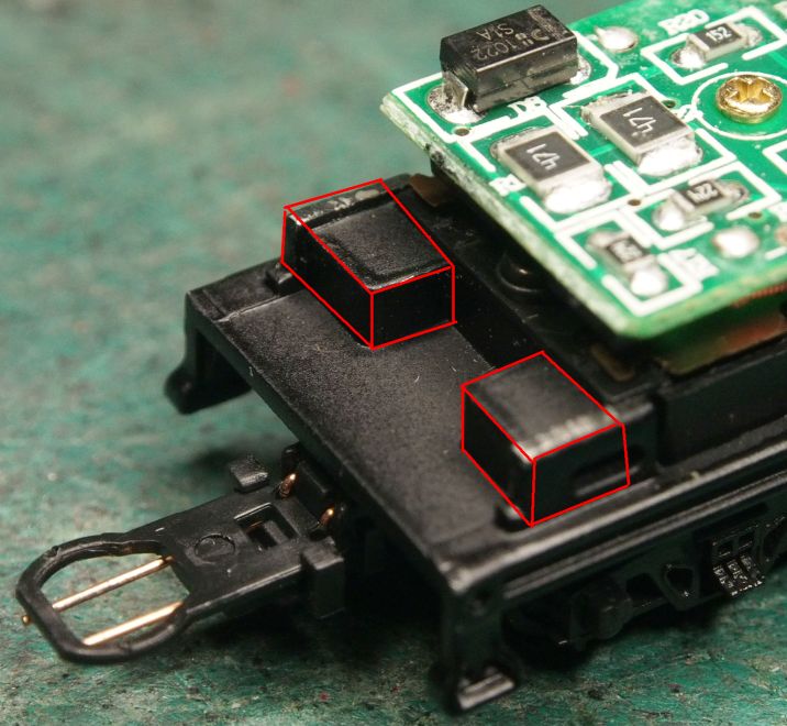
    Now for the only major work, two lumps of metal at the front of the chassis need to be removed (marked in red).
    dccc_1.jpg

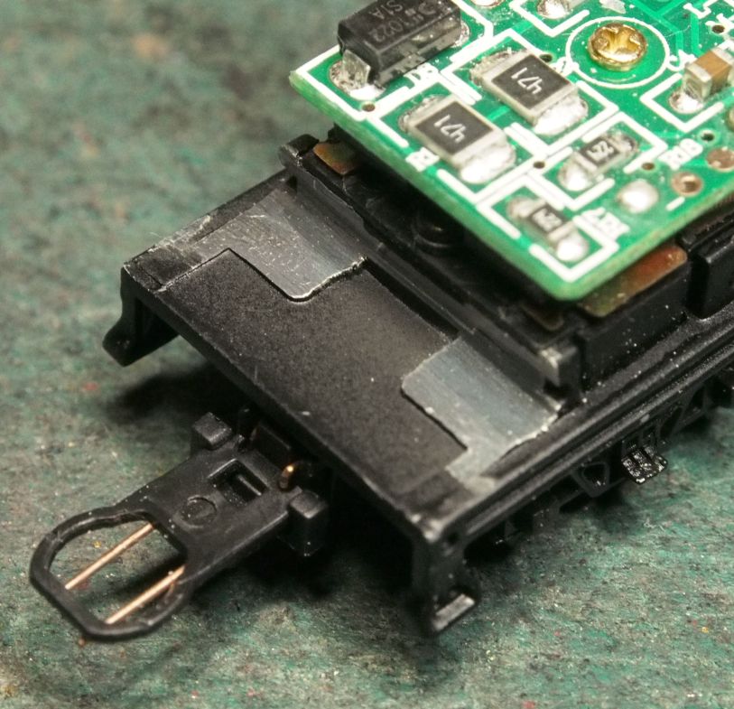
    You are aiming for this.
    dccc_2.jpg

    The new body should now fit onto the chassis. The lead from the loco passes through the hole at the front of the body.
    You can retain the original coupler, or remove it and fit a Microtrains 1015 as before.
    The gap between loco and tender is less than before, but it should go round most curves.
    dccc_3.jpg


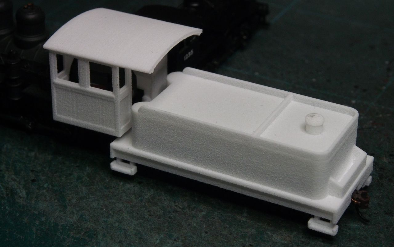
    Note - I have designed two tenders for this conversion.
    The Low one is the same height as the DC version. This has a hole in the coal space to allow room for the plug. This can be hidden with a coal load.
    The High one is 2mm taller than the DC one. The plug is completely hidden, but the tender top is smooth with no coal space. This can also be hidden with a coal load.
     
    Last edited: Dec 10, 2013
  13. So ,,,, how do I go about purchasing these conversion peices?????
     
  14. hclloydjr
    hclloydjr Member
    I would like to use your products to kit bash a K-27 "Mudhen" as close to the prototype to be believable. What do you think of my plan?
     
  15. hclloydjr
    hclloydjr Member
    i WOULD STILL LIKE TO KNOW HOW i CAN ORDER THESE PARTS FOR THE CONVERSION OF THE LOCO AND TENDER.
     
  16. Akarinn
    Akarinn Member
    Do you know if newer Bachmann 2-8-0 DCC tender chassis still fit your DCC tender versions? On Bachmann's website they have a part's diagram for the 2-8-0 that matches the tender from your picture. However the page is listed as Version before 2017. https://estore.bachmanntrains.com/index.php?main_page=index&cPath=70_80&sort=20a&page=4
    I was thinking of pre-ordering some Bachmann 2-8-0s that are supposed to be coming out at the end of the year and this kit. On the outside the upcoming ones look the same as older ones, but with with way DCC technology has advanced since 2017 who knows how the inside of the tender changed. If you don't know I can always try emailing Bachmann.